HP High-End Firewalls System Management and Maintenance Configuration Guide Part number: 5998-2634 Software version: F1000-E/Firewall module: R3166 F5000-A5: R3206 Document version: 6PW101-20120706
Legal and notice information © Copyright 2012 Hewlett-Packard Development Company, L.P. No part of this documentation may be reproduced or transmitted in any form or by any means without prior written consent of Hewlett-Packard Development Company, L.P. The information contained herein is subject to change without notice.
Contents Device information ······················································································································································· 1 Displaying device information ········································································································································· 1 Device info ····················································································································································
Performing storage medium operations ······················································································································· 21 Managing the space of a storage medium ········································································································ 21 Mounting/unmounting a storage medium ·········································································································· 21 Setting prompt modes ·····································
Eight output destinations and ten channels of system information ··································································· 48 Outputting system information by source module ······························································································ 49 Default output rules of system information ·········································································································· 49 System information format ····················································
Configuring the local clock as a reference source ····································································································· 91 Configuring optional parameters of NTP ···················································································································· 92 Specifying the source interface for NTP messages ···························································································· 92 Disabling an interface from receiving NTP messages ··
Configuring RSH ·························································································································································· 128 Configuration prerequisites ································································································································ 128 Configuration procedure ···································································································································· 128 RSH configurati
Support and other resources ·································································································································· 169 Contacting HP ······························································································································································ 169 Subscription service ············································································································································ 169 Relate
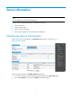
Device information NOTE: You can display device information through web. You can view the following information on the Device Info menu: • Device information • System resource state • Device interface information • Recent system logs (Recent five system logs are displayed) Displaying device information After you log in to the web interface, the Device Info page appears, as shown in Figure 1. Figure 1 Device overview Select the refresh mode from the Refresh Period drop-down box.
Device info Table 1 Device information configuration items Item Description Device Name Displays the device name. Product Information Displays the product information. Device Location Displays the location of the device. Contact Information Displays the contact information for device maintenance. SerialNum Displays the serial number of the device. Software Version Displays the software version of the device. Hardware Version Displays the hardware version of the device.
NOTE: To know more information about device interfaces, click the More hyperlink under the Device Interface Information area to enter the Device Management > Interface page to view and operate the interfaces. For more information, see Network Management Configuration Guide. Recent system logs Table 4 Recent system log configuration items Item Note Time Displays the time when the system logs are generated. Level Displays the level of the system logs.
System maintenance and debugging NOTE: The firewall supports system maintenance and debugging configuration only in the command line interface (CLI). System maintenance and debugging You can use the ping command and the tracert command to verify the current network connectivity, and use the debug command to enable debugging and thus to diagnose system faults based on the debugging information.
Ping configuration example Network requirements As shown in Figure 2, check whether an available route exists between Device A and Device C. If there is an available route exists between the two devices, get the detailed information of routes from Device A to Device C. Figure 2 Ping network diagram Configuration procedure # Use the ping command to display whether an available route exists between Device A and Device C. ping 1.1.2.2 PING 1.1.2.
1.1.1.2 1.1.1.1 Reply from 1.1.2.2: bytes=56 Sequence=3 ttl=254 time=1 ms Record Route: 1.1.2.1 1.1.2.2 1.1.1.2 1.1.1.1 Reply from 1.1.2.2: bytes=56 Sequence=4 ttl=254 time=1 ms Record Route: 1.1.2.1 1.1.2.2 1.1.1.2 1.1.1.1 Reply from 1.1.2.2: bytes=56 Sequence=5 ttl=254 time=1 ms Record Route: 1.1.2.1 1.1.2.2 1.1.1.2 1.1.1.1 --- 1.1.2.2 ping statistics --5 packet(s) transmitted 5 packet(s) received 0.00% packet loss round-trip min/avg/max = 1/11/53 ms The principle of ping –r is as shown in Figure 2. 1.
Figure 3 Tracert diagram The tracert function is implemented through ICMP, as shown in Figure 3: 1. The source (Device A) sends a packet with a TTL value of 1 to the destination (Device D). The UDP port of the packet is a port number that will not be used by any application of the destination. 2. The first hop (Device B) (the Layer 3 device that first receives the packet) responds by sending a TTL-expired ICMP error message to the source, with its IP address 1.1.1.2 encapsulated.
System debugging Introduction to system debugging The device provides various debugging functions. For the majority of protocols and features supported, the system provides corresponding debugging information to help users diagnose errors. The following two switches control the display of debugging information: • Protocol debugging switch, which controls protocol-specific debugging information. • Screen output switch, which controls whether to display the debugging information on a certain screen.
To do… Use the command… Remarks Optional Enable the terminal monitoring of system information The terminal monitoring on the console is enabled by default and that on the monitoring terminal is disabled by default.
0 packet(s) received 100.00% packet loss # No such a route exists. Use the tracert command to determine failed nodes. system-view [Firewall] ip ttl-expires enable [Firewall] ip unreachables enable [Firewall] tracert 1.1.2.2 traceroute to 1.1.2.2(1.1.2.2) 30 hops max,40 bytes packet, press CTRL_C to bre ak 1 1.1.1.
IP performance optimization configuration NOTE: The firewall supports configuring IP performance optimization only in the command line interface (CLI). Overview In some network environments, you can adjust the IP parameters to achieve best network performance.
Enabling the SYN Cookie feature As a general rule, the establishment of a TCP connection involves the following three handshakes: 1. The request originator sends a SYN message to the target server. 2. After receiving the SYN message, the target server establishes a TCP connection in the SYN_RECEIVED state, returns a SYN ACK message to the originator, and waits for a response. 3. After receiving the SYN ACK message, the originator returns an ACK message. Thus, the TCP connection is established.
To do... Use the command... Enable the protection against Naptha attack tcp anti-naptha enable Remarks Required Disabled by default. Optional Configure the maximum of TCP connections in a state tcp state { closing | established | fin-wait-1 | fin-wait-2 | last-ack | syn-received } connection-number number Configure the TCP state check interval tcp timer check-state timer-value 5 by default.
NOTE: The actual length of the finwait timer is determined by the following formula: Actual length of the finwait timer = (Configured length of the finwait timer – 75) + configured length of the synwait timer Configuring ICMP to send error packets Sending error packets is a major function of ICMP. In case of network abnormalities, ICMP packets are usually sent by the network or transport layer protocols to notify corresponding devices so as to facilitate control and management.
• When receiving a packet with the destination being local and transport layer protocol being UDP, if the packet’s port number does not match the running process, the device will send the source a “port unreachable” ICMP error packet. • If the source uses “strict source routing" to send packets, but the intermediate device finds that the next hop specified by the source is not directly connected, the device will send the source a “source routing failure” ICMP error packet.
To do… Use the command… Remarks Display ICMP statistics display icmp statistics Available in any view Display socket information display ip socket [ socktype sock-type ] [ task-id socket-id ] Available in any view Display FIB information display fib [ vpn-instance vpn-instance-name ] [ | { begin | include | exclude } regular-expression | acl acl-number | ip-prefix ip-prefix-name ] Available in any view Display FIB information matching the specified destination IP address display fib [ vpn-insta
File system management NOTE: You can manage files on the firewall only at the CLI. File system management overview The device stores files such as system software image files and configuration files that are necessary for operation in the storage media.
Performing directory operations You can perform an extensive set of directory operations, such creating or removing a directory, displaying the current working directory, displaying a specific directory, or displaying file information.
Performing file operations You can display the specified directory or file information; display file contents; rename, copy, move, remove, restore, and delete files. NOTE: You can create a file by copying, downloading or using the save command.
Deleting a file To do… Use the command… Move a file to the recycle bin or delete it permanently delete [ /unreserved ] file-url Remarks Required Available in user view CAUTION: • The files in the recycle bin still occupy storage space. To delete a file in the recycle bin, execute the reset recycle-bin command in the directory to which the file originally belongs. To save storage space, empty the recycle bin periodically with the reset recycle-bin command.
CAUTION: Execution of a batch file does not guarantee successful execution of every command in the batch file. If a command has error settings or the conditions for executing the command are not satisfied, this command fails to be executed, and the system skips to the next one. Performing storage medium operations Managing the space of a storage medium When the space of a storage medium becomes inaccessible, you can use the fixdisk command to restore the space of the storage medium.
To do… Use the command… Remarks Optional Unmount a storage medium umount device By default, a storage medium is automatically mounted and in mounted state when connected to the system. CAUTION: • When mounting or unmounting a storage medium, or performing file operations on it, do not unplug or switchover the storage medium or the card where the storage medium resides. Otherwise, the file system could be damaged.
# Display the files and the subdirectories under the test directory. dir Directory of cfa0:/test/ 0 drw- - Feb 16 2006 15:28:14 2540 KB total (2519 KB free) # Return to the upper directory. cd .. # Display the current working directory.
Configuration file management The device provides the configuration file management function. You can manage configuration files on the user-friendly CLI. Configuration file overview A configuration file stores device settings as a set of text commands. You can save the current configuration to a configuration file so that the configuration takes effect at the next startup. In addition, you can view the configuration information, and upload or download the configuration file to or from another device.
• Specify them when saving the current configuration. For more information, see “Saving the running configuration.” • Specify them when specifying the startup configuration file for the next system startup. For more information, see “Specifying a startup configuration file for the next system startup.” Startup with the configuration file The device takes the following steps when it starts up: 1.
Encrypting a configuration file Configuration file encryption enables you to encrypt a configuration file before saving it by using the save command. To read the encrypted configuration file, you must decrypt it with a legal key, thus protecting the configuration file. Two kinds of keys are supported to encrypt a configuration file.
NOTE: • The configuration file must have the .cfg extension. • During the execution of the save [ safely ] command, the startup configuration file to be used at the next system startup may be lost if the device reboots or the power supply fails. In this case, the device will boot with the null configuration, and after the device reboots, you need to re-specify a startup configuration file for the next system startup (see “Specifying a startup configuration file for the next system startup”).
Task Remarks Setting configuration rollback Required Configuring parameters for saving the current running configuration Before you save the running configuration either manually or automatically, you must configure the file path and filename prefix. After that, the system saves the current running configuration with the specified filename (filename prefix_serial number.cfg) to the specified path. The filename of a saved configuration file is like 20080620archive_1.cfg, or 20080620archive_2.cfg.
configuration files. This enables you to easily roll back the current configuration to a previous configuration state. Configure an automatic saving interval according to the storage medium performance and the frequency of configuration modification: • If the device configuration does not change frequently, manually save the running configuration as needed.
To do… Use the command… Remarks Enter system view system-view — Set configuration rollback configuration replace file filename Required CAUTION: Do not unplug and plug a card during configuration rollback (that is, the system is executing the configuration replace file command).
Backing up the configuration file to be used at the next startup Backing up the startup configuration file in the web Configuration file backup allows you to: • View the configuration file for next startup (including .cfg and .xml files). • Back up the configuration file for next startup (including .cfg and .xml files) to the PC of the current user. Select Device Management > Maintenance from the navigation tree, and click Backup to enter the configuration file backup page, as shown in Figure 7.
Deleting the configuration file to be used at the next startup Deleting the configuration file in the web You may need to delete a startup configuration file to be used at the next startup for one of the following reasons: • After you upgrade system software, the existing startup configuration files do not match the new system software. • Startup configuration files are corrupted, which is often caused by loading an incorrect configuration file.
Restoring the startup configuration file Restoring the startup configuration file in the web Configuration restoration allows you to: • Upload the .cfg file on the host of the current user to the device for the next startup • Upload the .xml file on the host of the current user to the device for the next startup, and delete the previous .
NOTE: • Before restoring a configuration file, ensure that the server is reachable, the server is enabled with TFTP service, and the client has read and write permission. • After execution of the command, use the display startup command (in user view) to verify that the filename of the configuration file to be used at the next system startup is the same with that specified by the filename argument.
Software upgrade configuration Software upgrade overview Software upgrade allows you to obtain a target system software image from the current host and set the file as the main or backup system software image to be used at the next reboot. A system software image is an application file used to boot the device. A main system software image is used to boot a device and a backup image file is used to boot a device only when the main image file is unavailable.
Upgrading software in the web interface NOTE: Software upgrade takes a period of time. During software upgrade, do not perform any operation on the web interface; otherwise, software upgrade may be interrupted. Select Device Management > Software Upgrade from the navigation tree to enter the software upgrade configuration page, as shown in Figure 11.
Upgrade method Upgrade object Description Software upgrade through a system reboot Boot ROM and system software You need to reboot the whole system to upgrade the software of a device. This causes running service interruption during the upgrade process, and is not recommended. System software Hotfix is a fast, cost-effective method to repair software defects of a device. Compared with software version upgrade, hotfix can upgrade the software without interrupting the running services of the device.
To do… Use the command… Remarks Specify the system software image for the next device boot boot-loader file file-url { main | backup } Required Available in user view. Software upgrade by installing hotfixes Hotfix is a fast, cost-effective method to repair software defects of a device. Compared with software upgrade, hotfix can upgrade the software without interrupting running services or rebooting the device. Basic concepts in hotfix 1.
Figure 12 Relationship between patch state changes and command actions Load DEACTIVE IDLE Delete Stop running Activate Delete Delete RUNNING ACTIVE Confirm running IDLE Install Do you want to continue running patches after reboot? [Y/N]:n Install Do you want to continue running patches after reboot? [Y/N]:y Uninstall RUNNING ACTIVE NOTE: Information about patch states is saved in file patchstate on the storage media. HP recommends that you do not operate this file. 1.
Patches in the DEACTIVE state have been loaded to the memory patch area but have not run in the system yet. Suppose that there are seven patches in the patch file to be loaded. After the seven patches successfully pass the version check and CRC check, they are loaded to the memory patch area and are in the DEACTIVE state. At this time, the patch states in the system are as shown in Figure 14. Figure 14 A patch file is loaded to the memory patch area 3.
Figure 16 Patches are running Hotfix configuration task list Task Install patches Remarks Installing a patch in one step Use either approach. Installing a patch step-by-step The step-by-step patch installation allows you to control the patch status. Uninstalling a patch step-by-step Optional Configuration prerequisites Patches are released per device model or card type. Before patching the system, you need to save the appropriate patch files to the storage media of the device using FTP or TFTP.
After you execute the command, the system displays the message “Do you want to continue running patches after reboot? [Y/N]:”. • Entering y or Y: All the specified patches are installed, and turn to the RUNNING state from IDLE. This equals execution of the commands patch location, patch load, patch active, and patch run. The patches remain RUNNING after system reboot. • Entering n or N: All the specified patches are installed and turn to the ACTIVE state from IDLE.
To do… Use the command… Configure the patch file location patch location patch-location Remarks Optional flash: by default NOTE: If you install a patch file by specifying the directory where the patch file locates, after the patch install command is executed, the system automatically changes patch file location specified with the patch location command to the directory specified by the patch-location argument of the patch install command.
NOTE: This operation is applicable to patches in the ACTIVE state only. Uninstalling a patch step-by-step Step-by-step patch uninstallation task list Task Remarks Stopping running patches Required Deleting patches Required Stopping running patches When you stop running a patch, the patch state becomes DEACTIVE, and the system runs in the way before it is installed with the patch.
• The IP address of the Firewall is 1.1.1.1/24, and IP address of TFTP Server is 2.2.2.2/24. The Firewall and TFTP server can reach each other. Figure 17 Network diagram of hotfix configuration Configuration procedure 1. Configure TFTP Server. The configuration varies depending on server type and the configuration procedure is omitted. • Enable the TFTP server function. • Save the patch file patch_xxx.bin to the directory of the TFTP server. 2.
Information center configuration NOTE: The firewall supports information center configuration only in the command line interface (CLI). Information center overview Introduction to information center Acting as the system information hub, information center classifies and manages system information, offering a powerful support for network administrators and developers in monitoring network performance and diagnosing network problems.
Figure 18 Information center diagram (default) NOTE: By default, the information center is enabled. An enabled information center affects the system performance in some degree due to information classification and output. Such impact becomes more obvious in the event that there is enormous information waiting for processing.
Table 8 Severity description Severity Severity value Description Emergency 0 The system is unusable.
Information channel number Default channel name Default output destination Description 8 channel8 Not specified Receives log, trap, and debugging information. 9 channel9 Log file Receives log, trap, and debugging information. NOTE: Configurations for the eight output destinations function independently and take effect only after the information center is enabled.
Output destinatio n Modules allowed Trap buffer TRAP LOG DEBUG Enabled/ disabled Severity Enabled/ disabled Severity Enabled/ disabled Severity default (all modules) Disabled Informati onal Enabled Warning Disabled Debug Log buffer default (all modules) Enabled Warning Disabled Debug Disabled Debug SNMP module default (all modules) Disabled Debug Enabled Warning Disabled Debug Web interface default (all modules) Enabled Debug Enabled Debug Disabled Debug Log file
timestamp in the system information as well as the timestamp format if it is included. The time stamp of the system information sent from the information center to the log host is with a precision of seconds, whereas that of the system information sent from the information center to the other destinations is with a precision of milliseconds. sysname Sysname is the system name of the current host. You can use the sysname command to modify the system name.
Configuring information center Information center configuration task list Complete the following tasks to configure information center: Task Remarks Outputting system information to the console Optional Outputting system information to a monitor terminal Optional Outputting system information to a log host Optional Outputting system information to the trap buffer Optional Outputting system information to the log buffer Optional Outputting system information to the SNMP module Optional Outputti
Enabling the display of system information on the console After setting to output system information to the console, you need to enable the associated display function to display the output information on the console.
Enabling the display of system information on a monitor terminal After setting to output system information to a monitor terminal, you need to enable the associated display function in order to display the output information on the monitor terminal.
To do… Use the command… Remarks Optional Specify the source IP address for the log information info-center loghost source interface-type interface-number By default, the source interface is determined by the matched route, and the primary IP address of this interface is the source IP address of the log information. Configure the format of the time stamp for system information output to the log host info-center timestamp loghost { date | no-year-date | none } Optional date by default.
To do… Use the command… Remarks Enter system view system-view — Enable information center info-center enable Name the channel with a specified channel number info-center channel channel-number name channel-name Optional Enabled by default. Optional For default channel names, see Table 9.
To do… Use the command… Configure the output rules of the system information info-center source { module-name | default } channel { channel-number | channel-name } [ debug { level severity | state state } * | log { level severity | state state } * | trap { level severity | state state } * ] * Configure the format of the timestamp info-center timestamp { debugging | log | trap } { boot | date | none } Remarks Optional See “Default output rules of system information.
Saving system information to a log file With the log file feature enabled, the log information generated by system can be saved to a specified directory with a predefined frequency. This allows you to check the operation history at any time to ensure that the device functions properly. Logs are saved into the logfile buffer before they are saved into a log file.
NOTE: • To ensure that the device works normally, use the info-center logfile size-quota command to set a logfile to be no smaller than 1 MB and no larger than 10 MB. • Use the info-center logfile switch-directory command to manually configure the directory to which a log file can be saved. The configuration will be invalid after system reboot.
To do… Use the command… Remarks Required Disable the port from generating link up/down logging information undo enable log updown By default, all ports are allowed to generate link up/down logging information when the port state changes. NOTE: With this feature applied to a port, when the state of the port changes, the system does not generate port link up/down logging information. In this case, you cannot monitor the port state changes conveniently.
Figure 19 Network diagram for outputting log information to a UNIX log host Configuration procedure Before the configuration, make sure that there is a route between Firewall and PC. Step1 Configure Firewall # Enable information center. system-view [Sysname] info-center enable # Specify the host with IP address 1.2.0.1/16 as the log host, use channel loghost to output log information (optional, loghost by default), and use local4 as the logging facility. [Sysname] info-center loghost 1.2.0.
NOTE: Be aware of the following issues while editing file /etc/syslog.conf: • Comments must be on a separate line and begin with the # sign. • No redundant spaces are allowed after the file name. • The logging facility name and the information level specified in the /etc/syslog.conf file must be identical to those configured on the device using the info-center loghost and info-center source commands; otherwise the log information may not be output properly to the log host. Step6 After log file info.
CAUTION: As the default system configurations for different channels are different, you need to disable the output of log, trap, and debugging information of all modules on the specified channel (loghost in this example) first and then configure the output rule as needed so that unnecessary information will not be output. # Configure the information output rule: allow log information of all modules with severity equal to or higher than informational to be output to the log host.
• The source modules are ARP and IP. Figure 21 Network diagram for sending log information to the console Configuration procedure # Enable information center. system-view [Sysname] info-center enable # Use channel console to output log information to the console (optional, console by default). [Sysname] info-center console channel console # Disable the output of log, trap, and debugging information of all modules on channel console.
Log management The log management feature enables you to store the system messages or logs generated by actions such as packet filtering to the log buffer or send them to the log hosts. The analysis and archiving of the logs can enable you to check the security holes of the firewall, when and who try to disobey security policies, and the types of the network attacks. The real-time logs can also be used to detect the ongoing attacks.
Table 11 Syslog configuration items Item Description Log Buffer Size Set the number of syslogs that can be stored in the log buffer. Clear Log To clear the logs in the log buffer, click this button. Log Host1 Log Host2 Log Host3 Set the IP addresses and port number of the syslog log hosts. The log information can be reported to the specified remote log hosts in the format of syslog, and you can specify up to four syslog log hosts.
Field Description SrcPort TCP/UDP source port number DestPort TCP/UDP destination port number StartTime Start time of a flow, in seconds, counted from 1970/1/1 0:0 EndTime End time of a flow, in seconds, counted from 1970/1/1 0:0 Prot Protocol carried over IP Operator Indicates the reason why a flow has ended Reserved For future applications Table 13 Packet format in flow logging version 3.
Configuring flow logging in the web interface Configuring flow logging Select Log Report > Userlog from the navigation tree to enter the page as shown in Figure 23. Figure 23 Flow logging Table 14 Flow logging configuration items Item Description Set the version of flow logging, including 1.0 and 3.0. Version IMPORTANT: Configure the flow logging version according to the capacity of the log receiving device.
Item Description Set to output flow logs to the information center in the format of system information. IMPORTANT: Output flows logs to information center • With this function enabled, flow logs will not be output to the specified userlog log host. • Outputting flow logs to the information center occupies the storage space of the device. Therefore, HP recommends that you output flow logs to the information center in case that there are a small amount of flow logs.
To do … Use the command… Configure flow logging version userlog flow export version version-number Remarks Optional The default flow logging version is 1.0 NOTE: Although the device supports both of the two versions, only one can be active at one time. Therefore, if you configure the flow logging version multiple times, the latest configuration takes effect. Configuring the source address for flow logging packets A source IP address is usually used to uniquely identify the sender of a packet.
To do … Use the command… Configure the IPv4 address and UDP port number of the log server userlog flow export [ vpn-instance vpn-instance-name ] host ipv4-address udp-port 2. Remarks Required Not configured by default.
Figure 25 Network diagram for flow logging 2. Configuration procedure • Configuration on Firewall. # Configure IP addresses for the interfaces according to the network diagram, and make sure that User and Firewall, and Firewall and the log server can reach each other. (The configuration procedure is omitted here.) # Set the flow logging version to 3.0. system-view [Firewall] userlog flow export version 3 # Export User's flow logs to the log server with IP address 1.2.3.6:2000.
Symptom 2: Flow logs cannot be exported to log server • Analysis: Both of the export approaches are configured. • Solution: Restore to the default, and then configure the IP address and UDP port number of the log server. Configuring session logging Session logging overview Session logging records users’ access information, IP address translation information, and traffic information, and can output the records in a specific format to a log host, allowing administrators to perform security auditing.
Configuring a session logging policy Select Log Report > Session Log > Log Policy from the navigation tree to display existing session logging policies, as shown in Figure 26. Then, click Add to enter the session logging policy configuration page, as shown in Figure 27. Figure 26 Session logging policy list Figure 27 Create a session logging policy Table 16 Configuration items for configuring a session logging policy Item Description Source Zone Specify the source zone and destination zone.
Figure 28 Global configuration page Table 17 Configuration items for setting session logging thresholds Item Description Set the time threshold for outputting session logging entries. Time Threshold With this argument set, log entries will be output for sessions whose lifetimes reach the specified time threshold. Set the traffic threshold for outputting session logging entries. It can be in number of packets or bytes.
Table 18 System log configuration items Item Description Time/Date Displays the time when the system logs are generated. Source Displays the module that generates the system logs. Level Displays the severity level of the system logs. For more information about severity levels, see Table 19. Description Displays the contents of the system logs. Table 19 System log severity level Severity level Description Value Emergency The system is unavailable.
Item Description Destination Zone Displays the destination zone of the connection. Destination IP Displays the destination IP address of the connection. Current Rate Displays the rate of the current connection. Current Connection Displays total number of the current connections. TCP Percentage Displays the percentage of TCP packets to the total packets. UDP Percentage Displays the percentage of UDP packets to the total packets.
Table 22 Blacklist log configuration items Item Description Time/Date Displays the time when the blacklist members are generated. Mode Displays whether the blacklist members are newly added or removed. Source IP Displays the IP addresses of the blacklist members. Displays the reasons why the addresses are added to the blacklist, including manual add and automatic add: Reason • Automatic add means that the system automatically adds the source IP address to the blacklist.
Item Description Displays the flow information. • If the protocol type is TCP or UDP, the displayed flow information is source IP address:source port-->destination IP address:destination port, for example, 1.1.1.2:1026-->1.1.2.10:69. Flow Information • If the protocol type is ICMP, the displayed flow information is source IP address-->destination IP address,ICMP type (ICMP code), for example, 1.1.1.2-->1.1.2.10, echo(8).
Figure 35 Flow logging 3.0 log report Table 24 Flow logging 1.0 configuration items Item Description Time/Date Displays the time and date when a flow log was generated. Protocol Type Displays the protocol type of a flow log. Displays flow information: • If the protocol type is TCP or UDP, the displayed flow information is source IP Flow Information address:source port-->destination IP address:destination port, for example, 1.1.1.2:1026-->1.1.2.10:69.
Table 25 Flow logging 3.0 configuration items Item Description Time/Date Displays the time and date when a flow log was generated. Protocol Type Displays the protocol type of a flow. Displays the flow information. • If the protocol type is TCP or UDP, the displayed flow information is source IP Flow Information address:source port-->destination IP address:destination port, for example, 1.1.1.2:1026-->1.1.2.10:69.
NTP configuration NOTE: The firewall supports NTP configuration only in the command line interface (CLI). NTP overview Defined in RFC 1305, the Network Time Protocol (NTP) synchronizes timekeeping among distributed time servers and clients. NTP runs over the User Datagram Protocol (UDP), using UDP port 123. The purpose of using NTP is to keep consistent timekeeping among all clock-dependent devices within the network so that the devices can provide diverse applications based on the consistent time.
How NTP works Figure 36 shows the basic workflow of NTP. Device A and Device B are interconnected over a network. They have their own independent system clocks, which need to be automatically synchronized through NTP. For an easy understanding, we assume that: • Prior to system clock synchronization between Device A and Device B, the clock of Device A is set to 10:00:00 am while that of Device B is set to 11:00:00 am.
This is only a rough description of the work mechanism of NTP. For details, refer to RFC 1305. NTP message format NTP uses two types of messages, clock synchronization message and NTP control message. An NTP control message is used in environments where network management is needed. As it is not a must for clock synchronization, it will not be discussed in this document. NOTE: All NTP messages mentioned in this document refer to NTP clock synchronization messages.
• Precision: an 8-bit signed integer indicating the precision of the local clock. • Root Delay: roundtrip delay to the primary reference source. • Root Dispersion: the maximum error of the local clock relative to the primary reference source. • Reference Identifier: Identifier of the particular reference source. • Reference Timestamp: the local time at which the local clock was last set or corrected.
Symmetric peers mode Figure 39 Symmetric peers mode A device working in the symmetric active mode periodically sends clock synchronization messages, with the Mode field in the message set to 1 (symmetric active); the device that receives this message automatically enters the symmetric passive mode and sends a reply, with the Mode field in the message set to 2 (symmetric passive). By exchanging messages, the symmetric peers mode is established between the two devices.
Multicast mode Figure 41 Multicast mode In the multicast mode, a server periodically sends clock synchronization messages to the user-configured multicast address, or, if no multicast address is configured, to the default NTP multicast address 224.0.1.1, with the Mode field in the messages set to 5 (multicast mode). Clients listen to the multicast messages from servers.
NOTE: • A CE is a device that has an interface directly connecting to the service provider (SP). A CE is not “aware of” the presence of the VPN. • A PE is a device directly connecting to CEs. In a network, all events related to VPN processing occur on the PE.
To do… Use the command… Remarks Enter system view system-view — Specify an NTP server for the device ntp-service unicast-server [ vpn-instance vpn-instance-name ] { ip-address | server-name } [ authentication-keyid keyid | priority | source-interface interface-type interface-number | version number ] * Required No NTP server is specified by default.
Configuring NTP broadcast mode The broadcast server periodically sends NTP broadcast messages to the broadcast address 255.255.255.255. After receiving the messages, the device working in NTP broadcast client mode sends a reply and synchronizes its local clock. For devices working in the broadcast mode, you need to configure both the server and clients.
To do… Use the command… Remarks Configure the device to work in the NTP multicast client mode ntp-service multicast-client [ ip-address ] Required Configuring the multicast server To do… Use the command… Remarks Enter system view system-view — Enter interface view interface interface-type interface-number Enter the interface used to send NTP multicast message.
NOTE: • Whether the ntp-service refclock-master command is supported depends on your device models. • Typically, the stratum level of the NTP server which is synchronized from an authoritative clock (such as an atomic clock) is set to 1. This NTP server operates as the primary reference source on the network; and other devices synchronize themselves to it.
To do… Use the command… Remarks Enter system view system-view — Enter interface view interface interface-type interface-number — Disable the interface from receiving NTP messages ntp-service in-interface disable Required An interface is enabled to receive NTP messages by default.
Configuration procedure Follow these steps to configure the NTP service access-control right to the local device: To do… Use the command… Remarks Enter system view system-view — Configure the NTP service access-control right for a peer device to access the local device ntp-service access { peer | query | server | synchronization } acl-number Required peer by default NOTE: The access-control right mechanism provides only a minimum degree of security protection for the system running NTP.
To do… Use the command… Remarks Enter system view system-view — Enable NTP authentication ntp-service authentication enable Configure an NTP authentication key ntp-service authentication-keyid keyid authentication-mode md5 value Configure the key as a trusted key ntp-service reliable authentication-keyid keyid Associate the specified key with an NTP server Required Disabled by default Required No NTP authentication key by default Required No authentication key is configured to be trusted by def
NOTE: The procedure of configuring NTP authentication on a server is the same as that on a client, and the same authentication key must be configured on both the server and client sides.
Root delay: 0.00 ms Root dispersion: 0.00 ms Peer dispersion: 0.00 ms Reference time: 00:00:00.000 UTC Jan 1 1900 (00000000.00000000) # Specify Firewall A as the NTP server of Firewall B so that Firewall B is synchronized to Firewall A. system-view [FirewallB] ntp-service unicast-server 1.0.1.11 # View the NTP status of Firewall B after clock synchronization. [FirewallB] display ntp-service status Clock status: synchronized Clock stratum: 3 Reference clock ID: 1.0.1.11 Nominal frequency: 64.
Figure 43 Network diagram for NTP symmetric peers mode configuration Firewall A 3.0 .1. 31/ 24 3. 0. 1. 32/ 24 3 .0. 1. 33/ 24 Firewall B Firewall C Configuration procedure 1. Configuration on Firewall A: # Specify the local clock as the reference source, with the stratum level of 2. system-view [FirewallA] ntp-service refclock-master 2 2. Configuration on Firewall B: # Specify Firewall A as the NTP server of Firewall B.
As shown above, Firewall B has been synchronized to Firewall C, and the clock stratum level of Firewall B is 2, while that of Firewall C is 1. # View the NTP session information of Firewall B, which shows that an association has been set up between Firewall B and Firewall C. [FirewallB] display ntp-service sessions source reference stra reach poll now offset delay disper ************************************************************************** [245] 3.0.1.31 [1234] 3.0.1.33 127.127.1.
# Configure Firewall D to work in the broadcast client mode and receive broadcast messages on GE 0/1. system-view [FirewallD] interface gigabitethernet 0/1 [FirewallD-GigabitEthernet0/1] ntp-service broadcast-client 3. Configuration on Firewall A. # Configure Firewall A to work in the broadcast client mode and receive broadcast messages on GE 0/1.
Figure 45 Network diagram for NTP multicast mode configuration Configuration procedure 1. Configuration on Firewall C: # Specify the local clock as the reference source, with the stratum level of 2. system-view [FirewallC] ntp-service refclock-master 2 # Configure Firewall C to work in the multicast server mode and send multicast messages through GE0/1. [FirewallC] interface gigabitethernet 0/1 [FirewallC-GigabitEthernet0/1] ntp-service multicast-server 2.
As shown above, Firewall D has been synchronized to Firewall C and the clock stratum level of Firewall D is 3, while that of Firewall C is 2. # View the NTP session information of Firewall D, which shows that an association has been set up between Firewall D and Firewall C. [FirewallD] display ntp-service sessions source reference stra reach poll now offset delay disper ************************************************************************** [1234] 3.0.1.31 127.127.1.0 2 254 64 62 -16.
************************************************************************** [1234] 3.0.1.31 127.127.1.0 2 255 64 26 -16.0 40.0 16.6 note: 1 source(master),2 source(peer),3 selected,4 candidate,5 configured Total associations : 1 NOTE: For how to configure IGMP and PIM, see Network Management Configuration Guide. Configuring NTP client/server mode with authentication Network requirements • The local clock of Firewall A is to be configured as a reference source, with the stratum level of 2.
# Specify the key as a trusted key. [FirewallA] ntp-service reliable authentication-keyid 42 # View the NTP status of Firewall B after clock synchronization. [FirewallB] display ntp-service status Clock status: synchronized Clock stratum: 3 Reference clock ID: 1.0.1.11 Nominal frequency: 64.0000 Hz Actual frequency: 64.0000 Hz Clock precision: 2^7 Clock offset: 0.0000 ms Root delay: 31.00 ms Root dispersion: 1.05 ms Peer dispersion: 7.81 ms Reference time: 14:53:27.371 UTC Sep 19 2005 (C6D94F67.
Figure 47 Network diagram for configuration of NTP broadcast mode with authentication Configuration procedure 1. Configuration on Firewall C: # Specify the local clock as the reference source, with the stratum level of 3. system-view [FirewallC] ntp-service refclock-master 3 # Configure NTP authentication.
Actual frequency: 64.0000 Hz Clock precision: 2^7 Clock offset: 0.0000 ms Root delay: 31.00 ms Root dispersion: 8.31 ms Peer dispersion: 34.30 ms Reference time: 16:01:51.713 UTC Sep 19 2005 (C6D95F6F.B6872B02) As shown above, Firewall D has been synchronized to Firewall C and the clock stratum level of Firewall D is 4, while that of Firewall C is 3. # View the NTP session information of Firewall D, which shows that an association has been set up between Firewall D and Firewall C.
RMON configuration NOTE: The firewall supports RMON configuration only in the command line interface (CLI). RMON overview Introduction Remote Monitoring (RMON) is used to realize the monitoring and management from the management devices to the managed devices on the network by implementing such functions as statistics and alarm.
limitation, may not cover all MIB information but four groups of information, alarm, event, history, and statistics, in most cases. The HP device adopts the second way and realizes the RMON agent function. With the RMON agent function, the management device can monitor all the traffic flowing among the managed devices on all connected LAN segments; obtain information about error statistics and performance statistics for network management.
variable is smaller than or equal to the lower threshold, a lower event is triggered. The event is then handled as defined in the event group. NOTE: If the value of a sampled alarm variable overpasses the same threshold multiple times, only the first one can cause an alarm event. That is, the rising alarm and falling alarm are alternate.
Configuring the RMON history statistics function Follow these steps to configure the RMON history statistics function: To do… Use the command… Remarks Enter system view system-view — Enter Ethernet interface view interface interface-type interface-number — Create an entry in the RMON history control table rmon history entry-number buckets number interval sampling-interval [ owner text ] Required NOTE: • The entry-number must be globally unique and cannot be used on another interface; otherwise,
To do… Use the command… Remarks Create an entry in the private alarm table rmon prialarm entry-number prialarm-formula prialarm-des sampling-interval { absolute | changeratio | delta } rising-threshold threshold-value1 event-entry1 falling-threshold threshold-value2 event-entry2 entrytype { forever | cycle cycle-period } [ owner text ] NOTE: • A new entry cannot be created if its parameters are identical with the corresponding parameters of an existing entry.
RMON configuration examples Ethernet statistics group configuration example Network requirements As shown in Figure 48, Agent is connected to a configuration terminal through its console port and to Server through Ethernet cables. Gather performances statistics on received packets on GigabitEthernet 0/1 through RMON Ethernet statistics table, and thus the administrator can view the statistics on packets received on the interface at any time.
History group configuration example Network requirements As shown in Figure 49, Agent is connected to a configuration terminal through its console port and to Server through Ethernet cables. Gather statistics on received packets on GigabitEthernet 0/1 every one minute through RMON history statistics table, and thus the administrator can view whether data burst happens on the interface in a short time.
packets : 8 , broadcast packets : 0 multicast packets : 6 , CRC alignment errors : 0 undersize packets : 0 , oversize packets : 0 fragments : 0 , jabbers : 0 collisions : 0 , utilization : 0 Sampled values of record 4 : dropevents : 0 , octets : 933 packets : 8 , broadcast packets : 0 multicast packets : 7 , CRC alignment errors : 0 undersize packets : 0 , oversize packets : 0 fragments : 0 , jabbers : 0 collisions : 0 , utilization : 0 Sampled values of record 5 : drop
Alarm group configuration example Network requirements As shown in Figure 50, Agent is connected to a console terminal through its console port and to an NMS across Ethernet. Do the following: • GigabitEthernet 0/1 is connected with the FTP server. Gather statistics on traffic of the server on Ethernet 1/1 with the sampling interval being five seconds. When traffic is above or below the thresholds, Agent sends the corresponding traps to the NMS.
display rmon alarm 1 AlarmEntry 1 owned by null is Valid. Samples type : delta Variable formula : 1.3.6.1.2.1.16.1.1.1.4.1 Sampling interval : 5(sec) Rising threshold : 100(linked with event 1) Falling threshold : 50(linked with event 2) When startup enables : risingOrFallingAlarm Latest value : 0 # Display statistics for interface GE0/1. display rmon statistics gigabitethernet 0/1 EtherStatsEntry 1 owned by user1-rmon is VALID.
SNMP configuration NOTE: The firewall supports SNMP configuration only in the command line interface (CLI). SNMP overview Simple Network Management Protocol (SNMP) offers the communication rules between a management device and the managed devices on the network; it defines a series of messages, methods and syntaxes to implement the access and management from the management device to the managed devices.
authentication on the device will simply be discarded. A community name performs a similar role as a password to regulate access from the NMS to the agent. • SNMPv2c uses community names for authentication. Compatible with SNMPv1, it extends the functions of SNMPv1. SNMPv2c provides more operation modes such as GetBulk and InformRequest; it supports more data types such as Counter64 and provides various error codes, thus being able to distinguish errors in more detail.
SNMP configuration As configurations for SNMPv3 differ substantially from those for SNMPv1 and SNMPv2c, their SNMP functionalities are introduced separately as follows.
Follow these steps to configure SNMPv1 and SNMPv2c: To do… Use the command… Remarks Enter system view system-view — Optional Disabled by default Enable the SNMP agent snmp-agent Configure SNMP agent system information snmp-agent sys-info { contact sys-contact | location sys-location | version { { v1 | v2c | v3 }* | all } } You can also enable the SNMP agent service by using any command that begins with snmp-agent except the snmp-agent calculate-password command Required Configure a local engine I
Configuring SNMP logging Introduction to SNMP logging SNMP logs the Get and Set operations that the NMS performs on the SNMP agent. When the GET operation is performed, the agent logs the IP address of the NMS, node name of the GET operation and OID of the node. When the SET operation is performed, the agent logs the IP address of the NMS, node name of the SET operation, OID of the node, the value configured and the error code and error index of the SET response.
occupy large device memory affect device performance, it is recommended not to enable the trap function for all modules but for the specific modules as needed. With the trap function enabled on a module, the traps generated by the module will be sent to the information center. The information center has seven information output destinations.
Configuration procedure After traps are sent to the SNMP module, the SNMP module saves the traps in the trap queue. You can set the size of the queue and the holding time of the traps in the queue, and you can also send the traps to the specified destination host (usually the NMS).
To do… Use the command… Display the modules that can send traps and whether their trap sending is enabled or not display snmp-agent trap-list Display SNMPv3 agent user information display snmp-agent usm-user [ engineid engineid | username user-name | group group-name ] * Display SNMPv1 or v2c agent community information display snmp-agent community [ read | write ] Display MIB view information for an SNMP agent display snmp-agent mib-view [ exclude | include | viewname view-name ] Remarks SNMPv1/
Ensure that the SNMP version specified in the snmp-agent target-host command is the same with that on the NMS; otherwise, the NMS cannot receive any trap. 2. Configuring the SNMP NMS With SNMPv1/v2c, the user needs to specify the read only community, the read and write community, the timeout time, and number of retries. The user can inquire and configure the device through the NMS. NOTE: The configurations on the agent and the NMS must match. 3.
[Sysname] snmp-agent sys-info location telephone-closet,3rd-floor # Enable sending of traps to the NMS with an IP address of 1.1.1.2/24, using public as the community name. [Sysname] snmp-agent trap enable [Sysname] snmp-agent target-host trap address udp-domain 1.1.1.2 udp-port 5000 params securityname public v3 2. Configuring the SNMP NMS SNMPv3 uses an authentication and privacy security model.
# Enable logging display on the terminal. (This function is enabled by default, so that you can omit this configuration). terminal monitor terminal logging # Enable the information center to output the system information with the severity level equal to or higher than informational to the console port. system-view [Sysname] info-center source snmp channel console log level informational # Enable SNMP logging on the agent to log the GET and SET operations of the NMS.
RSH configuration NOTE: The firewall supports configuring RSH only in the command line interface (CLI). RSH overview Remote shell (RSH) allows you to execute the internal and external commands provided by the operating system (OS) on a remote host that runs the RSH daemon. The firewall can serve as an RSH client and provides the rsh command as the tool for the RSH feature. Figure 56 shows a typical application scenario.
RSH configuration example Network requirements As shown in Figure 57, Firewall acts as the RSH client. The remote host runs Windows 2000 and has had RSH daemon service started. Set the time of the host remotely from Firewall. NOTE: Windows NT, 2000, XP, and 2003 are shipped with no RSH daemon. The RSH daemon must be obtained and installed separately on the remote host. Figure 57 Network diagram for RSH configuration Configuration procedure 1.
Figure 59 Services window c. Check for the Remote Shell Daemon entry. If it does not exist, install the daemon first. d. Look at the Status column to check whether the Remote Shell Daemon service is started. In this example, the service is not started yet. e. Double-click the Remote Shell Daemon service row, and then in the popped up Remote Shell Daemon Properties window, click Start to start the service, as shown in Figure 60. Figure 60 Remote Shell Daemon Properties window 2.
rsh 192.168.1.10 command time Trying 192.168.1.10 ... Press CTRL+K to abort The current time is: 6:56:42.
SSH2.0 configuration NOTE: The firewall supports SSH2.0 configuration only in the command line interface (CLI). SSH2.0 overview Introduction to SSH2.0 Secure Shell (SSH) offers an approach to logging into a remote device securely. By encryption and strong authentication, it protects devices against attacks such as IP spoofing and plain text password interception.
of “SSH-.-”. The primary and secondary protocol version numbers constitute the protocol version number, while the software version number is used for debugging. 3. The client receives and resolves the packet. If the protocol version of the server is lower but supportable, the client uses the protocol version of the server; otherwise, the client uses its own protocol version. 4.
inform the success or failure of the authentication. The device supports two publickey algorithms for digital signature: RSA and DSA. The following gives the steps of the authentication stage: 1. The client sends to the server an authentication request, which includes the username, authentication method (password authentication or publickey authentication), and information related to the authentication method (for example, the password in the case of password authentication). 2.
Configuring the firewall as an SSH server SSH server configuration task list Complete the following tasks to configure an SSH server: Task Remarks Generating a DSA or RSA key pair Required Enabling SSH server Required Configuring the user interfaces for SSH clients Required Configuring a client public key Required for publickey authentication users and optional for password authentication users Configuring an SSH user Optional Setting the SSH management parameters Optional Generating a DSA or
Enabling SSH server Follow these steps to enable SSH server: To do… Use the command… Remarks Enter system view system-view — Enable the SSH server function ssh server enable Required Disabled by default Configuring the user interfaces for SSH clients An SSH client accesses the device through a VTY user interface. Therefore, you must configure the user interfaces for SSH clients to allow SSH login. The configuration takes effect only for clients logging in after the configuration.
• Import it from the public key file: During the import process, the system will automatically convert the public key to a string coded using the Public Key Cryptography Standards (PKCS). Before importing the public key, you must upload the public key file (in binary) to the local host through FTP or TFTP. NOTE: • HP recommends you to configure a client public key by importing it from a public key file. • You can configure at most 20 client pubic keys on an SSH server.
To do… Create an SSH user, and specify the service type and authenticatio n mode Use the command… Remarks For Stelnet users ssh user username service-type stelnet authentication-type { password | { any | password-publickey | publickey } assign publickey keyname } Required For all users or SFTP users ssh user username service-type { all | sftp } authentication-type { password | { any | password-publickey | publickey } assign publickey keyname work-directory directory-name } Use either command.
To do… Use the command… Remarks Enter system view system-view — Enable the SSH server to support SSH1 clients ssh server compatible-ssh1x enable Optional By default, the SSH server supports SSH1 clients. Optional Set the RSA server key pair update interval ssh server rekey-interval hours 0 by default, that is, the RSA server key pair is not updated.
Configuring whether first-time authentication is supported When the device connects to the SSH server as an SSH client, you can configure whether the device supports first-time authentication. • With first-time authentication, when an SSH client not configured with the server host public key accesses the server for the first time, the user can continue accessing the server, and save the host public key on the client.
To do...
Figure 61 Firewall acts as server for password authentication Configuration procedure 1. Configure the SSH server # Generate RSA and DSA key pairs and enable SSH server. system-view [Firewall] public-key local create rsa [Firewall] public-key local create dsa [Firewall] ssh server enable # Configure an IP address for interface GigabitEthernet 0/0, which the SSH client will use as the destination for SSH connection.
Figure 62 SSH client configuration interface In the window shown in Figure 62, click Open. If the connection is normal, you will be prompted to enter the username and password. After entering the correct username (client001) and password (aabbcc), you can enter the configuration interface of Firewall. When the firewall acts as a server for publickey authentication Network requirements • The host (the SSH client) and Firewall (the SSH server) are directly connected through the Ethernet interfaces.
system-view [Firewall] public-key local create rsa [Firewall] public-key local create dsa [Firewall] ssh server enable # Configure an IP address for interface GigabitEthernet 0/0, which the SSH client will use as the destination for SSH connection. [Firewall] interface gigabitethernet 0/0 [Firewall-GigabitEthernet0/0] ip address 192.168.1.40 255.255.255.0 [Firewall-GigabitEthernet0/0] quit # Set the authentication mode for the user interfaces to AAA.
Figure 64 Generate a client key pair 1) While generating the key pair, you must move the mouse continuously and keep the mouse off the green process bar shown in Figure 65. Otherwise, the process bar stops moving and the key pair generating process will be stopped.
Figure 65 Generate a client key pair 2) After the key pair is generated, click Save public key and specify the file name as key.pub to save the public key.
Likewise, to save the private key, click Save private key. A warning window pops up to prompt you whether to save the private key without any protection. Click Yes and enter the name of the file for saving the key (private in this case). Figure 67 Generate a client key 4) NOTE: After generating a key pair on a client, you must transmit the saved public key file to the server through FTP or TFTP and have the configuration on the server done before continuing configuration of the client.
Figure 69 SSH client configuration interface 2) In the window shown in Figure 69, click Open. If the connection is normal, you will be prompted to enter the username. After entering the correct username (client002), you can enter the configuration interface of Firewall.
system-view [FirewallB] public-key local create rsa [FirewallB] public-key local create dsa [FirewallB] ssh server enable # Configure an IP address for interface GigabitEthernet 0/0, which the SSH client will use as the destination for SSH connection. [FirewallB] interface gigabitethernet 0/0 [FirewallB-GigabitEthernet0/0] ip address 10.165.87.136 255.255.255.0 [FirewallB-GigabitEthernet0/0] quit # Set the authentication mode for the user interfaces to AAA.
# Disable first-time authentication. [FirewallA] undo ssh client first-time # Configure the host public key of the SSH server. You can get the server host public key by using the display public-key local dsa public command on the server.
When the firewall acts as a client for publickey authentication Network requirements • As shown in Figure 71, Firewall A (the SSH client) logs into Firewall B (the SSH server) through the SSH protocol. • Publickey authentication is used, and the public key algorithm is DSA. Figure 71 Firewall acts as client for publickey authentication Configuration procedure 1. Configure the SSH server # Generate RSA and DSA key pairs and enable SSH server.
2. Configure the SSH client # Configure an IP address for interface GigabitEthernet0/0. system-view [FirewallA] interface gigabitethernet 0/0 [FirewallA-GigabitEthernet0/0] ip address 10.165.87.137 255.255.255.0 [FirewallA-GigabitEthernet0/0] quit # Generate a DSA key pair. [FirewallA] public-key local create dsa # Export the DSA public key to the file key.pub. [FirewallA] public-key local export dsa ssh2 key.
SFTP service NOTE: The firewall supports SFTP service configuration only in the CLI. SFTP overview The secure file transfer protocol (SFTP) is a new feature in SSH2.0. SFTP uses the SSH connection to provide secure data transfer. The device can serve as the SFTP server, allowing a remote user to log into the SFTP server for secure file management and transfer. The device can also server as an SFTP client, enabling a user to login from the device to a remote device for secure file transfer.
Configuring the SFTP connection idle timeout period Once the idle period of an SFTP connection exceeds the specified threshold, the system automatically tears the connection down, so that a user cannot occupy a connection for nothing.
Follow these steps to enable the SFTP client: To do… Establish a connection to the remote SFTP server and enter SFTP client view Use the command… Establish a connection to the remote IPv4 SFTP server and enter SFTP client view sftp server [ port-number ] [ identity-key { dsa | rsa } | prefer-ctos-cipher { 3des | aes128 | des } | prefer-ctos-hmac { md5 | md5-96 | sha1 | sha1-96 } | prefer-kex { dh-group-exchange | dh-group1 | dh-group14 } | prefer-stoc-cipher { 3des | aes128 | des } | prefer-stoc-hmac { m
To do… Use the command… Remarks Delete a directory from the SFTP server rmdir remote-path&<1-10> Optional Working with SFTP files SFTP file operations include: • Changing the name of a file • Downloading a file • Uploading a file • Displaying a list of the files • Deleting a file Follow these steps to work with SFTP files: Remarks To do… Use the command… Enter SFTP client view sftp [ ipv6 ] server [ port-number ] [ identity-key { dsa | rsa } | prefer-ctos-cipher { 3des | aes128 | des } |
To do… Use the command… Remarks Enter SFTP client view sftp [ ipv6 ] server [ port-number ] [ identity-key { dsa | rsa } | prefer-ctos-cipher { 3des | aes128 | des } | prefer-ctos-hmac { md5 | md5-96 | sha1 | sha1-96 } | prefer-kex { dh-group-exchange | dh-group1 | dh-group14 } | prefer-stoc-cipher { 3des | aes128 | des } | prefer-stoc-hmac { md5 | md5-96 | sha1 | sha1-96 } ] * Display a list of all commands or the help information of an SFTP client command help [ all | command-name ] Required Execut
system-view [FirewallB] public-key local create rsa [FirewallB] public-key local create dsa [FirewallB] ssh server enable # Enable the SFTP server. [FirewallB] sftp server enable # Configure an IP address for interface GigabitEthernet 0/0, which the client will use as the destination for SSH connection. [FirewallB] interface gigabitethernet 0/0 [FirewallB-GigabitEthernet0/0] ip address 192.168.0.1 255.255.255.
# Establish a connection with the remote SFTP server and enter SFTP client view. sftp 192.168.0.1 identity-key rsa Input Username: client001 Trying 192.168.0.1 ... Press CTRL+K to abort Connected to 192.168.0.1 ... The Server is not authenticated. Continue? [Y/N]:y Do you want to save the server public key? [Y/N]:n sftp-client> # Display files under the current directory of the server, delete file z, and check that the file has been deleted successfully.
sftp-client> dir -rwxrwxrwx 1 noone nogroup 1759 Aug 23 06:52 config.cfg -rwxrwxrwx 1 noone nogroup 225 Aug 24 08:01 pubkey2 -rwxrwxrwx 1 noone nogroup 283 Aug 24 07:39 pubkey drwxrwxrwx 1 noone nogroup 0 Sep 01 06:22 new -rwxrwxrwx 1 noone nogroup 225 Sep 01 06:55 pub drwxrwxrwx 1 noone nogroup 0 Sep 02 06:33 new2 # Download the pubkey2 file from the server and save it as local file public.
Configuration procedure 1. Configure the SFTP server # Generate RSA and DSA key pairs and enable the SSH server. system-view [Firewall] public-key local create rsa [Firewall] public-key local create dsa [Firewall] ssh server enable # Enable the SFTP server. [Firewall] sftp server enable # Configure an IP address for interface GigabitEthernet0/0, which the client will use as the destination for SSH connection.
Figure 74 SFTP client interface 162
Virtual device management NOTE: The firewall supports virtual device management only in the web interface. Virtual device management overview The virtual device feature allows you to divide a physical firewall into several logical firewalls. Creating virtual devices can provide firewall rental services. You can configure different security policies for different virtual devices, providing private route forwarding plane and security services for virtual device users.
Configuring a virtual device Configuration task list Perform the tasks in Table 29 to configure a virtual device. Table 29 Virtual device configuration task list Task Description Required Creating a virtual device You can add a member to a virtual device only after the virtual device is created. The virtual root device exists by default, so you do not need to create it. Optional After you add a specified Layer 3 interface to the created virtual device, the interface will be managed by the virtual device.
Table 30 Configuration items for creating a virtual device Item Virtual Device ID Virtual Device Name Description A virtual device ID is globally unique. 1 is the ID reserved for the virtual root device, and other virtual devices cannot use it. A virtual device name is globally unique. Root is the name reserved for the virtual root device, and other virtual devices cannot use it. Return to Virtual device configuration task list.
Figure 78 VLAN members Table 32 VLAN member configuration items Item Description Select the virtual device to be configured. Virtual Device The virtual device list contains all virtual devices that have been created, including the virtual root device. Configure the VLAN members to be added to the current virtual device. VLAN Range Click the icon in the Operation column corresponding to the virtual device to be configured, and type the VLAN range for the virtual device in the VLAN Range column.
Virtual device configuration example Network requirements Divide a physical firewall into two virtual devices and rent them to customer A and customer B respectively. • Layer 3 networking: Customer A and customer B have their own Layer 3 Ethernet interfaces. • Layer 2 networking: Customer A can use VLAN 100 through VLAN 205 and VLAN 300 through VLAN 310; customer B can use VLAN 50 through VLAN 80, VLAN 400, and VLAN 500 through VLAN 530. • Create two virtual devices Virtual_DevA and Virtual_DevB.
# Add interface GigabitEthernet1/1 to Virtual_DevA, and add GigabitEthernet1/2 to Virtual_DevB. • Select Device Management > Virtual Device > Interface from the navigation tree. • Select GigabitEthernet1/1 in the Interface Member column. • Select Virtual_DevA from the Virtual Device drop-down list. • Select GigabitEthernet1/1 from the Interface Member column. • Select Virtual_DevB from the Virtual Device drop-down list. • Click Apply. 3. Add VLAN members to the virtual devices.
Support and other resources Contacting HP For worldwide technical support information, see the HP support website: http://www.hp.
Conventions This section describes the conventions used in this documentation set. Command conventions Convention Description Boldface Bold text represents commands and keywords that you enter literally as shown. Italic Italic text represents arguments that you replace with actual values. [] Square brackets enclose syntax choices (keywords or arguments) that are optional. { x | y | ... } Braces enclose a set of required syntax choices separated by vertical bars, from which you select one.
Network topology icons Represents a generic network device, such as a router, switch, or firewall. Represents a routing-capable device, such as a router or Layer 3 switch. Represents a generic switch, such as a Layer 2 or Layer 3 switch, or a router that supports Layer 2 forwarding and other Layer 2 features. Represents a firewall chassis or a firewall module. Port numbering in examples The port numbers in this document are for illustration only and might be unavailable on your device.
Index BCDEFHILNOPRSTUV Displaying and maintaining RMON,111 B Displaying and maintaining SNMP,123 Backing up the configuration file to be used at the next startup,31 Displaying and maintaining SSH,141 Displaying device information,1 C E Configuration file overview,24 Example for file operations,22 Configuring a virtual device,164 Configuring access-control rights,93 F Configuring an SFTP client,154 File system management overview,17 Configuring an SFTP server,153 H Configuring ICMP to send err
RSH configuration example,129 Specifying a startup configuration file for the next system startup,30 RSH overview,128 SSH client configuration examples,148 S SSH server configuration examples,141 Saving the running configuration,25 SSH2.