
R3166-R3206-HP High-End Firewalls System Management and Maintenance Configuration Guide-6PW101


103
**************************************************************************
[1234] 3.0.1.31 127.127.1.0 2 255 64 26 -16.0 40.0 16.6
note: 1 source(master),2 source(peer),3 selected,4 candidate,5 configured
Total associations : 1
NOTE:
For how to configure IGMP and PIM, see
Network Management Configuration Guide
.
Configuring NTP client/server mode with authentication
Network requirements
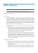
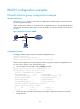
• The local clock of Firewall A is to be configured as a reference source, with the stratum level of 2.
• Firewall B works in the client mode and Firewall A is to be used as the NTP server of Firewall B, with
Firewall B as the client.
• NTP authentication is to be enabled on both Firewall A and Firewall B.
Figure 46 Network diagram for configuration of NTP client/server mode with authentication
Configuration procedure
1. Configuration on Firewall A:
# Specify the local clock as the reference source, with the stratum level of 2.
<FirewallA> system-view
[FirewallA] ntp-service refclcok-master 2
2. Configuration on Firewall B:
<FirewallB> system-view
# Enable NTP authentication on Firewall B.
[FirewallB] ntp-service authentication enable
# Set an authentication key.
[FirewallB] ntp-service authentication-keyid 42 authentication-mode md5 aNiceKey
# Specify the key as a trusted key.
[FirewallB] ntp-service reliable authentication-keyid 42
# Specify Firewall A as the NTP server.
[FirewallB] ntp-service unicast-server 1.0.1.11 authentication-keyid 42
Before Firewall B can synchronize its clock to that of Firewall A, you need to enable NTP authentication
for Firewall A.
Perform the following configuration on Firewall A:
# Enable NTP authentication.
[FirewallA] ntp-service authentication enable
# Set an authentication key.
[FirewallA] ntp-service authentication-keyid 42 authentication-mode md5 aNiceKey