
R3166-R3206-HP High-End Firewalls System Management and Maintenance Configuration Guide-6PW101


105
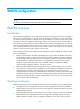
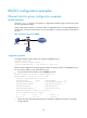
Figure 47 Network diagram for configuration of NTP broadcast mode with authentication
Configuration procedure
1. Configuration on Firewall C:
# Specify the local clock as the reference source, with the stratum level of 3.
<FirewallC> system-view
[FirewallC] ntp-service refclock-master 3
# Configure NTP authentication.
[FirewallC] ntp-service authentication enable
[FirewallC] ntp-service authentication-keyid 88 authentication-mode md5 123456
[FirewallC] ntp-service reliable authentication-keyid 88
# Specify Firewall C as an NTP broadcast server, and specify an authentication key.
[FirewallC] interface gigabitethernet 0/1
[FirewallC-GigabitEthernet0/1] ntp-service broadcast-server authentication-keyid 88
2. Configuration on Firewall D:
# Configure NTP authentication.
<FirewallD> system-view
[FirewallD] ntp-service authentication enable
[FirewallD] ntp-service authentication-keyid 88 authentication-mode md5 123456
[FirewallD] ntp-service reliable authentication-keyid 88
# Configure Firewall D to work in the NTP broadcast client mode.
[FirewallD] interface gigabitethernet 0/1
[FirewallD-GigabitEthernet0/1] ntp-service broadcast-client
Now, Firewall D can receive broadcast messages through GE0/1, and Firewall C can send broadcast
messages through Ethernet 1/1. Upon receiving a broadcast message from Firewall C, Firewall D
synchronizes its clock to that of Firewall C.
# View the NTP status of Firewall D after clock synchronization.
[FirewallD] display ntp-service status
Clock status: synchronized
Clock stratum: 4
Reference clock ID: 3.0.1.31
Nominal frequency: 64.0000 Hz