
R3166-R3206-HP High-End Firewalls System Management and Maintenance Configuration Guide-6PW101


7
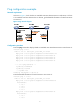
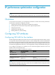
Figure 3 Tracert diagram
The tracert function is implemented through ICMP, as shown in Figure 3:
1. The source (Device A) sends a packet with a TTL value of 1 to the destination (Device D). The UDP
port of the packet is a port number that will not be used by any application of the destination.
2. The first hop (Device B) (the Layer 3 device that first receives the packet) responds by sending a
TTL-expired ICMP error message to the source, with its IP address 1.1.1.2 encapsulated. In this
way, the source device can get the address (1.1.1.2) of the first Layer 3 device.
3. The source device sends a packet with a TTL value of 2 to the destination device.
4. The second hop (Device C) responds with a TTL-expired ICMP error message, which gives the
source device the address (1.1.2.2) of the second Layer 3 device.
5. The above process continues until the ultimate destination device is reached. No application of the
destination uses this UDP port. Therefore, the destination replies a port unreachable ICMP error
message with the destination IP address 1.1.3.2.
6. When the source device receives the port unreachable ICMP error message, it knows that the
packet has reached the destination, and it can get the addresses of all the Layer 3 devices involved
to get to the destination device (1.1.1.2, 1.1.2.2, 1.1.3.2).
Configuring tracert
Follow these steps to configure tracert:
To do… Use the command…
Remarks
Enter system view system-view —
Enable sending of ICMP timeout
packets
ip ttl-expires enable
Required
Disabled by default.
Enable sending of ICMP
destination unreachable packets
ip unreachables enable
Required
Disabled by default.
Display the routes from source to
destination
tracert [ -a source-ip | -f first-ttl | -m
max-ttl | -p port | -q packet-number |
-vpn-instance vpn-instance-name | -w
timeout ] * host
Required
Available in any view