
R3166-R3206-HP High-End Firewalls System Management and Maintenance Configuration Guide-6PW101


167
Virtual device configuration example
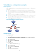
Network requirements
Divide a physical firewall into two virtual devices and rent them to customer A and customer B
respectively.
• Layer 3 networking: Customer A and customer B have their own Layer 3 Ethernet interfaces.
• Layer 2 networking: Customer A can use VLAN 100 through VLAN 205 and VLAN 300 through
VLAN 310; customer B can use VLAN 50 through VLAN 80, VLAN 400, and VLAN 500 through
VLAN 530.
• Create two virtual devices Virtual_DevA and Virtual_DevB.
• Add VLAN 100 through VLAN 205 and VLAN 300 through VLAN 310 to Virtual_DevA, and add
VLAN 50 through VLAN 80, VLAN 400, and VLAN 500 through VLAN 530 to Virtual_DevB.
• Add Layer 3 Ethernet interface GigabitEthernet1/1 to Virtual_DevA, and add Layer 3 Ethernet
interface GigabitEthernet1/2 to Virtual_DevB.
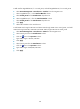
Figure 81 Network diagram for virtual device configuration
Configuration procedure
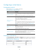
1. Create virtual devices.
# Create Virtual_DevA.
• Select Device Management > Virtual Device > Configuration from the navigation tree, and then
click Add.
• Type virtual device ID 2.
• Type virtual device name Virtual_DevA.
• Click Apply.
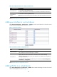
# Create Virtual_DevB.
• Click Add on the Add Virtual Device page.
• Type virtual device ID 3.
• Type virtual device name Virtual_DevB.
• Click Apply.
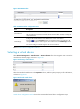
2. Add interfaces to the virtual devices.