
R3166-R3206-HP High-End Firewalls System Management and Maintenance Configuration Guide-6PW101


72
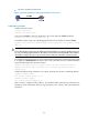
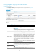
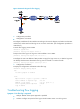
Figure 25 Network diagram for flow logging
2. Configuration procedure
• Configuration on Firewall.
# Configure IP addresses for the interfaces according to the network diagram, and make sure that User
and Firewall, and Firewall and the log server can reach each other. (The configuration procedure is
omitted here.)
# Set the flow logging version to 3.0.
<Firewall> system-view
[Firewall] userlog flow export version 3
# Export User's flow logs to the log server with IP address 1.2.3.6:2000.
[Firewall] userlog flow export host 1.2.3.6 2000
# Configure the source IP address of UDP packets carrying flow logs as 2.2.2.2, so that the log server
can identify that the actions described in the log were on Firewall or on other Firewalls.
[Firewall] userlog flow export source-ip 2.2.2.2
3. Configuration verification
# Display the configuration and statistics about flow logs.
<Firewall> display userlog export
nat:
No userlog export is enabled
flow:
Export Version 3 logs to log server : enabled
Source address of exported logs : 2.2.2.2
Address of log server : 1.2.3.6 (port: 2000)
total Logs/UDP packets exported : 112/87
Logs in buffer : 6
Troubleshooting flow logging
Symptom 1: No flow log is exported
• Analysis: Neither of the export approach is specified.
• Solution: Configure to export the flow logs to the information center or to the log server.