HP High-End Firewalls VPN Configuration Guide Part number: 5998-2632 Software version: F1000-E/Firewall module: R3166 F5000-A5: R3206 Document version: 6PW101-20120706
Legal and notice information © Copyright 2012 Hewlett-Packard Development Company, L.P. No part of this documentation may be reproduced or transmitted in any form or by any means without prior written consent of Hewlett-Packard Development Company, L.P. The information contained herein is subject to change without notice.
Contents GRE configuration ························································································································································ 1 GRE overview ···································································································································································· 1 GRE security options ·································································································································
Protocols and standards ······································································································································· 40 Configuring IPsec in the web interface ························································································································ 41 Configuration task list ··········································································································································· 41 Configuring an IPse
Key algorithm types············································································································································· 120 Asymmetric key algorithm applications ············································································································ 120 Configuring the local asymmetric key pair ··············································································································· 121 Creating an asymmetric key pair ······
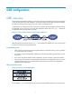
GRE configuration GRE overview Generic Routing Encapsulation (GRE) is a protocol designed for encapsulating and carrying the packets of one network layer protocol (for example, IP or IPX) over another network layer protocol (for example, IP). GRE is a tunneling technology and serves as a Layer 3 tunneling protocol. A GRE tunnel is a virtual point-to-point connection for transferring encapsulated packets. Packets are encapsulated at one end of the tunnel and de-encapsulated at the other end.
Figure 3 Format of an X packet encapsulated for transmission over an IP tunnel IP header GRE header X payload Passenger protocol Encapsulation protocol Transport protocol These are the terms involved: • Payload: Packet that needs to be encapsulated and transmitted. • Passenger protocol: Protocol that the payload packet uses, X in the example. • Encapsulation or carrier protocol: Protocol used to encapsulate the payload packet, that is, GRE.
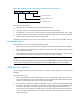
GRE applications Multi-protocol communications through a single-protocol backbone Figure 4 Multi-protocol communications through a single-protocol backbone Novell IPX protocol Group 1 Novell IPX protocol Group 2 Internet Device A Device B GRE tunnel IP protocol Team 1 IP protocol Team 2 In the example shown in Figure 4, Group 1 and Group 2 are local networks running Novell IPX, and Team 1 and Team 2 are local networks running IP.
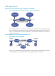
VPN establishment by connecting discontinuous subnets Figure 6 Connect discontinuous subnets with a tunnel to form a VPN In the example as shown in Figure 6, Group 1 and Group 2 running Novell IPX are deployed in different cities. They can constitute a trans-WAN virtual private network (VPN) through the tunnel.
Configuration task list Perform the tasks in Table 1 to configure a GRE over IPv4 tunnel. Table 1 GRE over IPv4 tunnel configuration task list Task Creating a GRE tunnel Remarks Required Create a tunnel interface and configure GRE tunnel related parameters. Optional Configuring a route through the tunnel Each end of the tunnel must have a route (static or dynamic) through the tunnel to the other end, so that GRE encapsulated packets can be forwarded normally.
Table 2 GRE tunnel configuration items Item Description Tunnel Interface Specify the number of the tunnel interface. Specify the IP address and subnet mask of the tunnel interface. IP/Mask IMPORTANT: When configuring a static route on the tunnel interface, make sure that the destination IP address of the static route is not in the subnet of the tunnel interface. Zone Tunnel Source IP/Interface Specify the security zone to which the tunnel interface belongs.
Figure 10 Network diagram for a GRE over IPv4 tunnel Configuration procedure NOTE: Before the configuration, make sure that Firewall A and Firewall B can reach each other. 1. Configure Firewall A # Configure an IPv4 address for interface GigabitEthernet 0/1. • Select Device Management > Interface from the navigation tree and then click the interface GigabitEthernet 0/1. • Select Static Address for IP Configuration. • Type IP address 10.1.1.1. • Select network mask 24 (255.255.255.0).
2. Configure Firewall B # Configure an IPv4 address for interface GigabitEthernet 0/1. • Select Device Management > Interface from the navigation tree and then click the interface GigabitEthernet 0/1. • Select Static Address for IP Configuration. • Type IP address 10.1.3.1. • Select network mask 24 (255.255.255.0). • Click Apply. icon of # Configure an IP address for interface GigabitEthernet 1/1, the physical interface of the tunnel. • Click the icon of interface GigabitEthernet 1/1.
• If you configure a source interface for a tunnel interface, the tunnel interface takes the primary IP address of the source interface as its source address. • You can enable or disable the checksum function at both ends of the tunnel as needed. If the checksum function is enabled at the local end but not at the remote end, the local end calculates the checksum of a packet to be sent but does not check the checksum of a received packet.
To do… Use the command… Enable the GRE packet checksum function gre checksum Remarks Optional Disabled by default Optional By default, no key is configured for a GRE tunnel interface. Configure the key for the GRE tunnel interface gre key key-number Configure a route for packet forwarding through the tunnel For IP routing configuration, see Network Management Configuration Guide. The two ends of a tunnel must have the same key or have no key at the same time.
[FirewallA] interface gigabitEthernet 0/0 [FirewallA-GigabitEthernet0/0] ip address 1.1.1.1 255.255.255.0 [FirewallA-GigabitEthernet0/0] quit # Create an interface named Tunnel 0. [FirewallA] interface tunnel 0 # Configure an IPv4 address for interface Tunnel 0. [FirewallA-Tunnel0] ip address 10.1.2.1 255.255.255.0 # Configure the tunnel encapsulation mode. [FirewallA-Tunnel0] tunnel-protocol gre # Configure the source address of interface Tunnel 0 to be the IP address of GigabitEthernet 0/0.
# Display the tunnel interface status on Firewall A and Firewall B respectively. [FirewallA] display interface tunnel 0 Tunnel0 current state: UP Line protocol current state: UP Description: Tunnel0 Interface The Maximum Transmit Unit is 1476 Internet Address is 10.1.2.1/24 Primary Encapsulation is TUNNEL, service-loopback-group ID not set. Tunnel source 1.1.1.1, destination 2.2.2.
Reply from 10.1.1.1: bytes=56 Sequence=1 ttl=255 time=2 ms Reply from 10.1.1.1: bytes=56 Sequence=2 ttl=255 time=2 ms Reply from 10.1.1.1: bytes=56 Sequence=3 ttl=255 time=2 ms Reply from 10.1.1.1: bytes=56 Sequence=4 ttl=255 time=2 ms Reply from 10.1.1.1: bytes=56 Sequence=5 ttl=255 time=2 ms --- 10.1.1.1 ping statistics --5 packet(s) transmitted 5 packet(s) received 0.
IKE Configuration IKE overview Built on a framework defined by the Internet Security Association and Key Management Protocol (ISAKMP), Internet Key Exchange (IKE) provides automatic key negotiation and SA establishment services for IP Security (IPsec), simplifying the application, management, configuration and maintenance of IPsec dramatically. Instead of transmitting keys directly across a network, IKE peers transmit keying materials between them, and calculate shared keys respectively.
Figure 12 IKE exchange process in main mode As shown in Figure 12, the main mode of IKE negotiation in phase 1 involves three pairs of messages: • SA exchange, used for negotiating the security policy. • Key exchange, used for exchanging the Diffie-Hellman public value and other values like the random number. Key data is generated in this stage. • ID and authentication data exchange, used for identity authentication and the whole SA exchange.
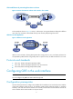
Relationship between IKE and IPsec Figure 13 Relationship between IKE and IPsec Figure 13 illustrates the relationship between IKE and IPsec: • IKE is an application layer protocol using UDP and functions as the signaling protocol of IPsec. • IKE negotiates SAs for IPsec and delivers negotiated parameters and generated keys to IPsec. • IPsec uses the SAs established through IKE negotiation for encryption and authentication of IP packets.
Task Remarks Optional An IKE proposal defines a set of attributes describing how IKE negotiation should take place. You may create multiple IKE proposals with different preferences. The preference of an IKE proposal is represented by its sequence number, and the smaller the sequence number, the higher the preference. Configuring an IKE proposal Two peers must have at least one pair of matched IKE proposals for successful IKE negotiation.
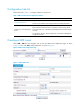
Figure 14 IKE global configuration page Table 4 Global IKE configuration items Item Description Type a name for the local security gateway. IKE Local Name If the local device acts as the IKE negotiation initiator and uses the security gateway name for IKE negotiation, you must configure this argument on the local device. Then, the local device sends its gateway name as identification to its peer and the peer uses the locally configured remote gateway name to authenticate the local device.
Figure 16 Add an IKE proposal Table 5 IKE proposal configuration items Item Description Type the IKE proposal number. IKE Proposal Number The number also stands for the priority of the IKE proposal, with a smaller value meaning a higher priority. During IKE negotiation, the system matches IKE proposals in order of proposal number, starting from the smallest one. Authentication Method • Preshared Key—Uses the pre-shared key method. Authentication Algorithm • SHA1—Uses HMAC-SHA1.
Item Description Type the ISAKMP SA lifetime of the IKE proposal. Before an SA expires, IKE negotiates a new SA. As soon as the new SA is set up, it takes effect immediately and the old one will be cleared automatically when it expires. SA Lifetime IMPORTANT: If the SA lifetime expires, the system automatically updates the ISAKMP SA. DH calculation in IKE negotiation takes time, especially on low-end devices.
Configuring an IKE peer Select VPN > IKE > Peer from the navigation tree to display existing IKE peers, as shown in Figure 19. Then, click Add to configure an IKE peer, as shown in Figure 20. Figure 19 IKE peer list Figure 20 Add an IKE peer Table 7 IKE peer configuration items Item Description Peer Name Type a name for the IKE peer.
Item Description Select the IKE negotiation mode in phase 1, which can be Main or Aggressive. IMPORTANT: IKE Negotiation Mode If the IP address of one end of an IPsec tunnel is obtained dynamically (for example, when the user uses a dialup line), the IKE negotiation mode must be Aggressive. In this case, SAs can be established as long as the username and password are correct. Select the local ID type in IKE negotiation phase 1.
Item Description Enable the NAT traversal function for IPsec/IKE. In main mode, IKE does not support NAT traversal and therefore this item is unavailable. Enable the NAT traversal function IMPORTANT: To save IP addresses, ISPs often deploy NAT gateways on public networks to allocate private IP addresses to users.
Field Description Status of the SA. Possible values include: • RD (ready)—Indicates that the SA has already been established and is ready for use. • ST (stayalive)—Indicates that the local end is the tunnel negotiation initiator. • RL (replaced)—Indicates that the tunnel has been replaced and will be cleared soon. • FD (fading)—Indicates that the soft lifetime expires but the tunnel is still in use. The tunnel will be deleted when the hard lifetime expires.
• Type peer as the peer name. • Select Main as the negotiation mode. • Select IP Address as the local ID type. • Type 2.2.2.2 as the remote gateway IP address. • Select Pre-Shared Key and type abcde as the pre-shared key. • Click Apply. # Create an IKE proposal numbered 10. • Select VPN > IKE > Proposal from the navigation tree and then click Add. • Type 10 as the IKE proposal number. • Select Preshared Key as the authentication method. • Select MD5 as the authentication algorithm.
Complete the following tasks to configure IKE: Task Remarks Configuring a name for the local security gateway Optional Optional Configuring an IKE proposal Required if you want to specify an IKE proposal for an IKE peer to reference.
To do… Use the command… Remarks Enter system view system-view — Create an IKE proposal and enter its view ike proposal proposal-number Required Specify an encryption algorithm for the IKE proposal encryption-algorithm { 3des-cbc | aes-cbc [ key-length ] | des-cbc } Optional Specify an authentication method for the IKE proposal authentication-method { pre-share | rsa-signature } Optional Specify an authentication algorithm for the IKE proposal authentication-algorithm { md5 | sha } Optional
• Enable NAT traversal. If there is NAT gateway on the path for tunneling, you must configure NAT traversal at the two ends of the IPsec tunnel, because one end may use a public address while the other end uses a private address. • Specify the dead peer detection (DPD) detector for the IKE peer.
To do… Use the command… Remarks Optional Configure the IP addresses of the two ends By default, it is the primary IP address of the interface referencing the security policy.
with the TIMEOUT tag (if it does not have the tag), or be deleted along with the IPsec SAs it negotiated (when it has the tag already). Follow these steps to set the keepalive timers: To do… Use the command… Remarks Enter system view system-view — Set the ISAKMP SA keepalive interval ike sa keepalive-timer interval seconds Set the ISAKMP SA keepalive timeout ike sa keepalive-timer timeout seconds Required No keepalive packet is sent by default. Required No keepalive packet is sent by default.
Follow these steps to configure a DPD detector: To do… Use the command… Remarks Enter system view system-view — Create a DPD detector and enter its view ike dpd dpd-name Required Set the DPD interval interval-time interval-time Set the DPD packet retransmission interval time-out time-out Optional 10 seconds by default Optional 5 seconds by default Disabling next payload field checking The Next payload field is in the generic payload header of the last payload of the IKE negotiation message (th
The two Firewalls use the pre-shared key authentication method. Figure 23 Network diagram for configuring IKE in main mode with pre-shared key authentication Configuration procedure NOTE: Ensure that Firewall A and Firewall B can reach each other. 1. Configure Firewall A # Configure ACL 3101 to identify traffic from subnet 10.1.1.0/24 to subnet 10.1.2.0/24. system-view [FirewallA] acl number 3101 [FirewallA-acl-adv-3101] rule permit ip source 10.1.1.0 0.0.0.255 destination 10.1.2.0 0.0.0.
# Set the authentication algorithm to MD5. [FirewallA-ike-proposal-10] authentication-algorithm md5 # Set the authentication method to pre-shared key. [FirewallA-ike-proposal-10] authentication-method pre-share # Set the ISAKMP SA lifetime to 5,000 seconds. [FirewallA-ike-proposal-10] sa duration 5000 [FirewallA-ike-proposal-10] quit # Create an IPsec policy that uses IKE negotiation. [FirewallA] ipsec policy map1 10 isakmp # Reference IPsec proposal tran1.
[FirewallB-ipsec-proposal-tran1] esp authentication-algorithm sha1 [FirewallB-ipsec-proposal-tran1] quit # Create IKE peer peer. [FirewallB] ike peer peer # Set the pre-shared key. [FirewallB-ike-peer-peer] pre-shared-key abcde # Specify the IP address of the peer security gateway. [FirewallB-ike-peer-peer] remote-address 1.1.1.1 [FirewallB-ike-peer-peer] quit # Create an IPsec policy that uses IKE negotiation.
Firewall A and Firewall B has only one pair of matching IKE proposals. Matching IKE proposals do not necessarily use the same ISAKMP SA lifetime setting. # Send traffic from subnet 10.1.1.0/24 to subnet 10.1.2.0/24. Firewall A starts IKE negotiation with Firewall B when receiving the first packet. # View the SAs established in the two IKE negotiation phases. [FirewallA] display ike sa total phase-1 SAs: connection-id 1 peer flag phase doi ---------------------------------------------------------1 2.
[outbound ESP SAs] spi: 89389742 (0x553faae) proposal: ESP-ENCRYPT-DES ESP-AUTH-SHA1 sa duration (kilobytes/sec): 1843200/3600 sa remaining duration (kilobytes/sec): 1843199/3590 max received sequence-number: 5 udp encapsulation used for nat traversal: N Troubleshooting IKE When configuring parameters to establish an IPsec tunnel, enable IKE error debugging to locate configuration problems: debugging ike error Invalid user ID Symptom Invalid user ID.
Solution For the negotiation in phase 1, look up the IKE proposals for a match. For the negotiation in phase 2, check whether the parameters of the IPsec policies applied on the interfaces are matched, and whether the referred IPsec proposals have a match in protocol, encryption and authentication algorithms. Failing to establish an IPsec tunnel Symptom The expected IPsec tunnel cannot be established.
IPsec configuration IPsec overview IP Security (IPsec) is a security framework defined by the Internet Engineering Task Force (IETF) for securing IP communications. It is a Layer 3 Virtual Private Network (VPN) technology that transmits data in a secure tunnel established between two endpoints.
Basic concepts Security association A security association is an agreement negotiated between two communicating parties called IPsec peers. It comprises a set of parameters for data protection, including security protocols, encapsulation mode, authentication and encryption algorithms, and privacy keys and their lifetime. SAs can be set up manually or through IKE. An SA is unidirectional. At least two SAs are needed to protect data flows in a bidirectional communication.
Authentication algorithms and encryption algorithms 1. Authentication algorithms IPsec uses hash algorithms to perform authentication. A hash algorithm produces a fixed-length digest for an arbitrary-length message. IPsec peers respectively calculate message digests for each packet. If the resulting digests are identical, the packet is considered intact. IPsec supports two hash algorithms for authentication: • MD5, which takes as input a message of arbitrary length and produces a 128-bit message digest.
Configuring IPsec in the web interface Configuration task list The firewall implements all the IPsec features previously described. The idea behind the implementation is as follows: 1. By configuring IPsec, provide different security services (authentication, encryption, or both) for different data flows. 2. IPsec depends on the rules in an ACL to identify data flows to be protected. Packets permitted by the ACL will be protected, while those denied will not.
Task Remarks Required Configure an IPsec policy by specifying the parameters directly or by referencing a created IPsec policy template. The web interface supports only IKE-dependent IPsec policies. Configuring an IPsec policy IMPORTANT: An IKE-dependent IPsec policy created by referencing a template cannot be used to initiate SA negotiation, but it can be used to respond to a negotiation request.
Figure 27 IPsec proposal configuration in suite mode Table 10 IPsec proposal configuration items in suite mode Item Description Proposal Name Type the name for the IPsec proposal. Select the encryption suite for the proposal. An encryption suite specifies the IP packet encapsulation mode, security protocol, and authentication and encryption algorithms to be used.
Item Encapsulation Mode Description Select the IP packet encapsulation mode for the IPsec proposal. Options include: • Tunnel—Uses the tunnel mode. • Transport—Uses the transport mode. Select the security protocol for the proposal. Options include: Security Protocol • AH—Uses the AH protocol. • ESP—Uses the ESP protocol. • AH-ESP—Uses ESP first and then AH. AH Authentication Algorithm Select the authentication algorithm for AH. This item is available when the security protocol is AH or AH-ESP.
Figure 29 IPsec policy template list Figure 30 IPsec policy template configuration page Table 12 Configuration items for an IPsec policy template Item Description Template Name Type the name for the IPsec policy template. Type the sequence number for the IPsec policy template. Sequence Number In an IPsec policy template group, an IPsec policy template with a smaller sequence number has a higher priority. Select the IKE peer for the IPsec policy template to reference.
Item Description Enable and configure the Perfect Forward Secrecy (PFS) feature or disable the feature. Options include: • dh-group1—Uses the 768-bit Diffie-Hellman group. • dh-group2—Uses the 1024-bit Diffie-Hellman group. • dh-group5—Uses the 1536-bit Diffie-Hellman group. • dh-group14—Uses the 2048-bit Diffie-Hellman group. PFS IMPORTANT: • dh-group14, dh-group5, dh-group2, and dh-group1 are in the descending order of security and calculation time.
Figure 32 IPsec policy configuration page Table 13 IPsec policy configuration items Item Description Policy Name Type the name for the IPsec policy. Type the sequence number for the IPsec policy. Sequence Number In an IPsec policy group, an IPsec policy with a smaller sequence number has a higher priority. Select the IPsec policy template to be referenced.
Item Description Enable and configure the Perfect Forward Secrecy (PFS) feature or disable the feature. Options include: • dh-group1—Uses the 768-bit Diffie-Hellman group. • dh-group2—Uses the 1024-bit Diffie-Hellman group. • dh-group5—Uses the 1536-bit Diffie-Hellman group. • dh-group14—Uses the 2048-bit Diffie-Hellman group. PFS IMPORTANT: • dh-group14, dh-group5, dh-group2, and dh-group1 are in the descending order of security and calculation time.
Figure 33 IPsec policy application Figure 34 IPsec policy application page Table 14 Configuration items for IPsec policy group application Item Description Interface Displays the interface to which you want to apply an IPsec policy group. Policy Select the IPsec policy group to be applied. Return to IPsec configuration task list. Viewing IPsec SAs Select VPN > IPSec > IPSec SA from the navigation tree to display brief information about established IPsec SAs, as shown in Figure 35.
Field Description Encryption Algorithm Encryption algorithm that the security protocol uses. Return to IPsec configuration task list. Viewing packet statistics Select VPN > IPSec > Statistics from the navigation tree to view packet statistics, as shown in Figure 36. Figure 36 Packet statistics Return to IPsec configuration task list.
Figure 37 Network diagram for IPsec configuration Configuration procedure 1. Configure Firewall A # Define an ACL to permit traffic from subnet 10.1.1.0/24 to subnet 10.1.2.0/24. • Select Firewall > ACL from the navigation tree, and then click Add. • Type 3101 as the ACL number. • Select the match order of Config. • Click Apply. • From the ACL list, select ACL 3101 and click the corresponding ACL rule configuration page. • Select Permit from the Operation drop-down box.
• Select ESP as the security protocol. • Select SHA1 as the ESP authentication algorithm. • Select DES as the ESP encryption algorithm. • Click Apply. # Configure the IKE peer. • Select VPN > IKE > Peer from the navigation tree and then click Add. • Type peer as the peer name. • Select Main as the negotiation mode. • Select IP Address as the local ID type. • Type 2.2.3.1 as the IP address of the remote gateway. • Select Pre-Shared Key and type abcde as the pre-shared key. • Click Apply.
• Select Deny from the Operation drop-down box. • Click Apply. # Configure a static route to Host A. • Select Network > Routing Management > Static Routing from the navigation tree, and then click Add. • Type 10.1.1.0 as the destination IP address. • Type 255.255.255.0 as the mask. • Select GigabitEthernet 0/2 as the outbound interface. • Click Apply. # Configure an IPsec proposal named tran1. • Select VPN > IPSec > Proposal from the navigation tree and then click Add.
Verification After the configuration, packets to be exchanged between subnet 10.1.1.0/24 and subnet 10.1.2.0/24 will trigger the negotiation of SAs by IKE. After IKE negotiation succeeds and the IPsec SAs are established, traffic between subnet 10.1.1.0/24 and subnet 10.1.2.0/24 will be protected by IPsec. IPsec VPN configuration wizard in the web interface The IPsec VPN policy configuration wizard provides a way to configure IPsec VPNs easily.
Figure 40 IPsec VPN policy configuration wizard: 1/4 Select a node type according to the position of the firewall in the network. Configuring a center node 1. Select Center Node from the first page of the IPsec VPN policy configuration wizard and then click Next to enter the page shown in Figure 41.
Figure 41 IPsec VPN policy configuration wizard: 2/4 (center node) 2. Configure the items on the page. Table 16 describes the configuration items. Table 16 Configuration items on a center node: 2/4 Item Description Type the name for the IPsec VPN. IMPORTANT: If you type abc here, the wizard will create an IKE peer named abc_peer, an IPsec proposal named abc_prop, an IPsec template named abc_temp and numbered 1, an IPsec policy named abc_poli and numbered 1, and an IKE proposal numbered 10.
Figure 42 IPsec VPN policy configuration wizard: 3/4 (center node) 4. Configure the items on the page. Table 17 describes the configuration items. Table 17 Configuration items on a center node: 3/4 Item Description Select the encryption suite for the IPsec proposal. An encryption suite specifies the IP packet encapsulation mode, security protocol, and authentication and encryption algorithms to be used.
Figure 43 IPsec VPN policy configuration wizard: 4/4 (center node) 6. Click Finish to complete the configuration. The system will jump to the page that you can enter by selecting VPN > IPSec > IPSec Application from the navigation tree. Configuring a branch node 1. Select Branch Node from the first page of the IPsec VPN policy configuration wizard and then click Next to enter the page shown in Figure 44.
Figure 44 IPsec VPN policy configuration wizard: 2/4 (branch node) 2. Configure the items on the page. Table 18 describes the configuration items. Table 18 Configuration items on a branch node: 2/4 Item Description Type the name for the IPsec VPN. IMPORTANT: IPSec VPN Name If you type abc here, the wizard will create an IKE peer named abc_peer, an IPsec proposal named abc_prop, an IPsec policy named abc_poli and numbered 1, and an IKE proposal numbered 1.
3. Click Next to enter the next page, as shown in Figure 45. Figure 45 IPsec VPN policy configuration wizard: 3/4 (branch node) 4. Configure the items on the page. Table 19 describes the configuration items. Table 19 Configuration items on a branch node: 3/4 Item Description Source IP Address/Wildcard Specify the traffic to be protected by giving the source IP address and wildcard, destination IP address and wildcard, and the protocol type.
Item Description Pre-Shared Key Select the authentication method for IKE negotiation and specify the required argument. Options include: • Pre-Shared Key—Uses the pre-shared key authentication method. • PKI Domain—Uses the RSA signature authentication method. Available PKI PKI Domain domains are those configured by selecting VPN > PKI > Domain from the navigation tree. Select this check box to enable dead peer detection (DPD).
Figure 47 IPsec VPN policy configuration wizard: 2/4 (peer node) 2. Configure the items on the page. Table 20 describes the configuration items. Table 20 Configuration items on a peer node: 2/4 Item Description Type the name for the IPsec VPN. IMPORTANT: IPSec VPN Name If you type abc here, the wizard will create an IKE peer named abc_peer, an IPsec proposal named abc_prop, an IPsec policy named abc_poli and numbered 1, and an IKE proposal numbered 1.
Figure 48 IPsec VPN policy configuration wizard: 3/4 (peer node) 4. Configure the items on the page. Table 21 describes the configuration items. Table 21 Configuration items on a peer node: 3/4 Item Description Source IP Address/Wildcard Specify the traffic to be protected by giving the source IP address and wildcard, destination IP address and wildcard, and the protocol type.
Item Description Pre-Shared Key Select the authentication method for IKE negotiation and specify the required argument. Options include: • Pre-Shared Key—Uses the pre-shared key authentication method. • PKI Domain—Uses the RSA signature authentication method. Available PKI PKI Domain domains are those configured by selecting VPN > PKI > Domain from the navigation tree. Select this check box to enable dead peer detection (DPD).
Tunnel interface-based IPsec, or routing-based IPsec, depends on the routing mechanism to select the data flows to be protected. To implement tunnel interface-based IPsec, configure IPsec profiles and apply them to IPsec tunnel interfaces (see “Implementing tunnel interface-based IPsec“). By using IPsec profiles, this IPsec implementation method simplifies IPsec VPN configuration and management, and improves the scalability of large VPN networks.
• In the outbound direction, if a permit statement is matched, IPsec considers that the packet requires protection and continues to process it. If a deny statement is matched or no match is found, IPsec considers that the packet does not require protection and delivers it to the next function module. • In the inbound direction, all IPsec packets matching a permit statement are processed by IPsec, and all non-IPsec packets that match a permit statement are discarded.
rule 0 permit ip source 3.3.3.0 0.0.0.255 destination 1.1.2.0 0.0.0.255 rule 1 deny ip # ipsec policy test 1 isakmp security acl 3001 ike-peer aa proposal 1 2. Mirror image ACLs To ensure that SAs can be set up and the traffic protected by IPsec can be processed correctly at the remote peer, on the remote peer, create a mirror image ACL rule for each ACL rule created at the local peer. As shown in Figure 50, ACL rules on Router B are mirror images of the rules on Router A.
Figure 51 Non-mirror image ACLs 3. Protection modes Data flows can be protected in the following modes: • Standard mode, in which one tunnel protects one data flow. The data flow permitted by an ACL rule is protected by one tunnel that is established solely for it. • Aggregation mode, in which one tunnel protects all data flows permitted by all the rules of an ACL. This mode applies to only scenarios that use IKE for negotiation.
To do… Use the command… Remarks Specify the authentication algorithm for ESP esp authentication-algorithm { md5 | sha1 } Optional Specify the authentication algorithm for AH ah authentication-algorithm { md5 | sha1 } Optional MD5 by default MD5 by default Optional Tunnel mode by default Specify the IP packet encapsulation mode for the IPsec proposal encapsulation-mode { transport | tunnel } Transport mode applies only when the source and destination IP addresses of data flows match those of the
• The keys for the local and remote inbound and outbound SAs must be in the same format. For example, if the local inbound SA uses a key in characters, the local outbound SA and remote inbound and outbound SAs must use keys in characters. b. Configuration prerequisites Configure ACLs used for identifying protected traffic and IPsec proposals.. c.
NOTE: • An IPsec policy can reference only one ACL. If you apply multiple ACLs to an IPsec policy, only the last one takes effect. • A manual IPsec policy can reference only one IPsec proposal. To change an IPsec proposal for an IPsec policy, you must remove the proposal reference first. • If you configure a key in two modes: string and hexadecimal, only the last configured one will be used. • You cannot change the creation mode of an IPsec policy from manual to through IKE, or vise versa.
To do… Use the command… Remarks Optional Enable and configure the perfect forward secrecy feature for the IPsec policy pfs { dh-group1 | dh-group2 | dh-group5 | dh-group14 } Set the SA lifetime sa duration { time-based seconds | traffic-based kilobytes } Return to system view quit By default, the PFS feature is not used for negotiation. For more information about PFS, see the chapter “IKE configuration.” Optional By default, the global SA lifetime is used.
To do… Use the command… Remarks Optional Enable and configure the perfect forward secrecy feature for the IPsec policy pfs { dh-group1 | dh-group2 | dh-group5 | dh-group14 } Configure the SA lifetime sa duration { time-based seconds | traffic-based kilobytes } Return to system view quit By default, the PFS feature is not used for negotiation. For more information about PFS, see the chapter ” IKE configuration.” Optional By default, the global SA lifetime settings are used.
You can apply an IPsec policy group to a logical or physical interface to protect certain data flows. To cancel the IPsec protection, remove the application of the IPsec policy group. For each packet to be sent out an IPsec protected interface, the system looks through the IPsec policies in the IPsec policy group in ascending order of sequence numbers. If an IPsec policy matches the packet, the system uses the IPsec policy to protect the packet.
To do… Use the command… Remarks Enter system view system-view — Enable ACL checking of de-encapsulated IPsec packets ipsec decrypt check Optional Enabled by default Configuring the IPsec anti-replay function The IPsec anti-replay function protects networks against anti-replay attacks by using a sliding window mechanism called anti-replay window. This function checks the sequence number of each received IPsec packet against the current IPsec packet sequence number range of the sliding window.
Follow these steps to configure packet information pre-extraction: To do… Use the command… Remarks Enter system view system-view — Enter IPsec policy view or IPsec policy template view Enable packet information pre-extraction ipsec policy policy-name seq-number [ isakmp | manual ] ipsec policy-template template-name seq-number qos pre-classify Required Configure either command Required Disabled by default Implementing tunnel interface-based IPsec IPsec configuration task list The following is the
applied to an interface, for each packet arriving at the interface, the system checks the IPsec policies of the IPsec policy group in the ascending order of sequence numbers. One IPsec tunnel will be established for each data flow to be protected, and multiple IPsec tunnels may exist on an interface. An IPsec profile is similar to an IPsec policy. The difference is that an IPsec profile is uniquely identified by its name and it does not support ACL configuration.
To do… Use the command… Remarks Return to system view quit — Optional Set the global SA lifetime ipsec sa global-duration { time-based seconds | traffic-based kilobytes } 3600 seconds for time-based SA lifetime by default 1843200 kilobytes for traffic-based SA lifetime by default. Configuring an IPsec tunnel interface An IPsec tunnel interface uses IPsec as the encapsulation protocol. To configure an IPsec tunnel interface, complete the following tasks: 1.
To do… Use the command… Remarks Required Specify the source address or interface of the tunnel interface Specify the destination address of the tunnel interface source { ip-address | interface-type interface-number } destination ip-address By default, no source address or interface is specified for a tunnel interface. If you specify an interface, the tunnel interface will take the primary IP address of the source interface.
To do… Use the command… Remarks Required Enable packet information pre-extraction Disabled by default. qos pre-classify For more information about the command, see Network Management Command Reference. CAUTION: When the QoS policy applied to the physical outbound interface provides congestion management, IPsec packets arriving at the destination may be out of order. This may cause IPsec out of order to be dropped by the IPsec anti-replay function.
To do… Use the command… Remarks Display IPsec SA information display ipsec sa [ brief | duration | policy policy-name [ seq-number ] | remote ip-address ] Available in any view Display IPsec packet statistics display ipsec statistics [ tunnel-id integer ] Available in any view Display IPsec tunnel information display ipsec tunnel Available in any view Clear SAs reset ipsec sa [ parameters dest-address protocol spi | policy policy-name [ seq-number ] | remote ip-address ] Available in user view
# Create an IPsec proposal named tran1. [FirewallA] ipsec proposal tran1 # Specify the encapsulation mode as tunnel. [FirewallA-ipsec-proposal-tran1] encapsulation-mode tunnel # Specify the security protocol as ESP. [FirewallA-ipsec-proposal-tran1] transform esp # Specify the algorithms for the proposal. [FirewallA-ipsec-proposal-tran1] esp encryption-algorithm des [FirewallA-ipsec-proposal-tran1] esp authentication-algorithm sha1 [FirewallA-ipsec-proposal-tran1] quit # Create manual IPsec policy map1.
# Specify the encapsulation mode as tunnel. [FirewallB-ipsec-proposal-tran1] encapsulation-mode tunnel # Specify the security protocol as ESP. [FirewallB-ipsec-proposal-tran1] transform esp # Specify the algorithms for the proposal. [FirewallB-ipsec-proposal-tran1] esp encryption-algorithm des [FirewallB-ipsec-proposal-tran1] esp authentication-algorithm sha1 [FirewallB-ipsec-proposal-tran1] quit # Create a manual IPsec policy. [FirewallB] ipsec policy use1 10 manual # Apply the ACL.
# Define an ACL to identify data flows from subnet 10.1.1.0/24 to subnet 10.1.2.0/24. system-view [FirewallA] acl number 3101 [FirewallA-acl-adv-3101] rule permit ip source 10.1.1.0 0.0.0.255 destination 10.1.2.0 0.0.0.255 [FirewallA-acl-adv-3101] quit # Configure a static route to Host B. [FirewallA] ip route-static 10.1.2.0 255.255.255.0 GigabitEthernet 0/1 # Create an IPsec proposal named tran1. [FirewallA] ipsec proposal tran1 # Specify the encapsulation mode as tunnel.
# Configure a static route to Host A. [FirewallB] ip route-static 10.1.1.0 255.255.255.0 serial 2/2 # Create an IPsec proposal named tran1. [FirewallB] ipsec proposal tran1 # Specify the encapsulation mode as tunnel. [FirewallB-ipsec-proposal-tran1] encapsulation-mode tunnel # Specify the security protocol as ESP. [FirewallB-ipsec-proposal-tran1] transform esp # Specify the algorithms for the proposal.
To meet the requirements, configure an IPsec tunnel interface on each Firewall and configure a static route on each Firewall to route the packets destined to the peer to the IPsec tunnel interface for IPsec protection. Figure 53 Network diagram for setting up an IPsec tunnel with IPsec tunnel interfaces Configuation procedure a. Configure Firewall A # Name the local gateway Firewalla. system-view [FirewallA] ike local-name Firewalla # Configure an IKE peer named atob.
# Set the source interface of the tunnel to GigabitEthernet 0/2 on Tunnel 1. [FirewallA–Tunnel1] source GigabitEthernet 0/2 # Set the tunnel destination address to 1.1.1.1, the source address of the remote peer. [FirewallA–Tunnel1] destination 1.1.1.1 # Apply IPsec profile atob to tunnel interface Tunnel 1. [FirewallA–Tunnel1] ipsec profile atob [FirewallA–Tunnel1] quit # Configure a static route to Firewall B. [FirewallA] ip route-static 192.168.1.0 255.255.255.0 tunnel 1 b.
# Set the source interface of the tunnel to GigabitEthernet 0/2 on Tunnel 1. [FirewallB–Tunnel1] source GigabitEthernet 0/2 # Apply IPsec profile btoa to tunnel interface Tunnel 1. [FirewallB–Tunnel1] ipsec profile btoa [FirewallB–Tunnel1] quit # Configure a static route to Firewall A. [FirewallB] ip route-static 172.17.17.0 255.255.255.0 tunnel 1 c.
sour addr: 0.0.0.0/0.0.0.0 port: 0 protocol: IP dest addr: 0.0.0.0/0.0.0.
L2TP configuration L2TP overview The Layer 2 Tunneling Protocol (L2TP) is one of the most commonly used Virtual Private Dial-up Network (VPDN) tunneling protocol. Typical networking application of L2TP Figure 54 shows a typical VPDN built by using L2TP. Figure 54 VPDN built by using L2TP A VPDN built by using L2TP consists of the following components: • Remote system A remote system is usually a remote user’s host or a remote branch’s routing device that needs to access the VPDN network.
Basic concepts of L2TP Background of L2TP The point-to-point Protocol (PPP) defines an encapsulation mechanism that allows a point-to-point link to carry packets of various protocols. When PPP runs between a user and an NAS, the PPP session and the Layer 2 link terminate at the same physical device—the NAS.
Both control messages and PPP frames are transferred on the tunnel. L2TP uses hello packets to check a tunnel’s connectivity. The LAC and the LNS regularly send hello packets to each other. If no response packet is received within a given amount of time, the tunnel is torn down. Control message and data message L2TP supports two types of messages: Control messages and data messages. • Control messages are used in establishment, maintenance, and clearing of tunnels and sessions.
Figure 58 Client-initiated tunnel mode L2TP tunnel establishment process Figure 59 shows a typical L2TP network. Figure 59 Typical L2TP network RADIUS server RADIUS server IP network IP network PPPoE/ISDN Host A Host B WAN Device A LAC Device B LNS Host C Figure 60 depicts the setup procedure of an L2TP call in NAS-initiated mode.
Figure 60 L2TP call setup procedure LAC Device A Client LAC RADIUS server LNS Device B LNS RADIUS server (1) Call setup (2) PPP LCP setup (3) PPP or CHAP authenticaion (4) Access request (5) Access accept (6) Tunnel setup (7) PPP or CHAP authentication (challenge/response) (8) Authentication passes (9) User CHAP response, PPP negotiation parameter (10) Access request (11) Acesss accept (12) CHAP authentication twice (challenge/response) (13) Access request (14) Acesss accept (15) Authentication passes
14. The RADIUS server authenticates the access request and returns a response if the user passes authentication. 15. The LNS assigns an internal IP address to the remote user. The user can now access the internal resources of the enterprise network. L2TP features 1. Flexible identity authentication mechanism and high security L2TP itself does not provide security for connections. However, it has all the security features of PPP for it allows for PPP authentication (CHAP or PAP).
L2TP configuration task list Perform the tasks in Table 22 to configure L2TP on the LNS. Table 22 L2TP configuration task list Task Remarks Enabling L2TP Required Required Adding an L2TP group Create a L2TP group and configure L2TP group related parameters. Optional Displaying L2TP tunnel information View the L2TP tunnel information. Enabling L2TP Select VPN > L2TP > L2TP Config from the navigation tree to enter the L2TP configuration page, as shown in Figure 61.
Figure 62 Add an L2TP group Table 24 Configuration items for adding an L2TP group Item Description L2TP Group Name Specify the name of the L2TP group. Peer Tunnel Name Specify the peer name of the tunnel. Local Tunnel Name Specify the local name of the tunnel. Tunnel Authentication Authentication Password Enable or disable L2TP tunnel authentication in the group. If you enable tunnel authentication, you need to set the authentication password.
Item Description Authentication Method Select the authentication method for PPP users on the local end. You can select PAP or CHAP. If you do not select an authentication method, no authentication will be performed. Specify the ISP domain for PPP user authentication. You can: • Click Add to enter the page for adding an ISP domain. For more information, see Table 25. • Select an ISP domain and click Modify to enter the ISP domain modification page. For more information, see Table 25.
Item Description Specify whether to enable mandatory CHAP authentication between the LNS and client. Mandatory CHAP After the LAC authentications the client, the LNS may re-authenticate the client for higher security. With mandatory CHAP authentication configured on the local end, a VPN client that depends on a NAS to initiate tunneling requests is authenticated twice: once when accessing the NAS and once on the LNS by using CHAP.
Item Description Select the authorization server type for PPP users. • HWTACACS: Uses HWTACACS authorization. • Local: Uses local authorization. • None: No authorization exchange is performed. Every user Server Type Authorization Methods Primary is trusted and has the corresponding default rights of the system. • RADIUS: Uses RADIUS authorization. If you do not select any authorization method, the default authorization method of the ISP domain will be used, which is Local by default.
Item Description Specify the number of the IP address pool. IP Address Pool Number If you set the IP address pool number to 1, the name of the IP address pool is pool1. Start IP Specify the start IP address and end IP address of the IP address pool. End IP The number of addresses between the start IP address and end IP address must not exceed 1024. If you specify only the start IP address, the IP address pool will contain only one IP address, namely, the start IP address.
Figure 64 Network diagram for client-initiated VPN configuration Configuration procedure 1. Configure the VPN user Install the L2TP client software such as WinVPN Client on the host and connect the host to the Internet in dial-up mode. Then, perform the following configurations (the configuration procedure depends on the client software): • Specify the VPN username as vpdnuser and the password as Hello. • Set the Internet interface address of the security gateway as the IP address of the LNS.
• Select domain system. • Type 1 as the IP address pool number. • Type the start IP address 192.168.0.2. • Type the end IP address 192.168.0.100. • Click Apply to finish the IP address pool configuration and return to the L2TP group configuration page. • Select pool1 from the User Address drop-down list. • Select Enable from the Assign Address Forcibly drop-down list. • Click Apply.
Configuring basic L2TP capability An L2TP group is intended to represent a group of parameters and corresponds to one VPN user or one group of VPN users. This not only allows for flexible L2TP configuration on devices, but also facilitates one-to-one and one-to-many networking applications of LACs and LNSs. An L2TP group has only local significance. However, you need to ensure that the relevant settings of the corresponding L2TP groups on the LAC and LNS match respectively.
Configuring an LAC to transfer AVP data in hidden mode With L2TP, some parameters are transferred as attribute value pair (AVP) data. You can configure an LAC to transfer AVP data in hidden mode, namely, encrypt AVP data before transmission, for higher security.
NOTE: • For successful authentication of users, you also need to perform PPP configurations on the corresponding interface of the LAC, for example, the asynchronous serial interface connecting with users. • You must configure the authentication type for PPP users as PAP or CHAP on the user access interfaces. • For information about AAA configuration commands and remote AAA authentication method configuration, see Access Control Configuration Guide.
To do… Use the command… Specify the address pool for allocating an IP address to a VPN user, or assign an IP address to the user directly remote address { pool [ pool-number ] | ip-address } Remarks Optional By default, address pool 0 (the default address pool) is used.
With mandatory CHAP authentication configured, a VPN user that depends on a NAS to initiate tunneling requests is authenticated twice: once when accessing the NAS and once on the LNS by using CHAP. Follow these steps to configure mandatory CHAP authentication: To do… Use the command… Remarks Enter system view system-view — Enter L2TP group view l2tp-group group-number — Configure mandatory CHAP authentication Required mandatory-chap By default, CHAP authentication is not performed on an LNS.
• Mandatory LCP re-negotiation authentication is configured on the LNS and the virtual interface template requires authenticating PPP users. After you configure AAA on the LNS, the LNS can authenticate the identities (usernames and passwords) of VPN users for a second time. If a user passes the AAA authentication, the user can communicate with the LNS. Otherwise, the L2TP session will be removed. LNS side AAA configurations are similar to those on an LAC.
Configuring L2TP connection parameters These L2TP connection parameter configuration tasks apply to both LACs and LNSs and are optional. Configuring L2TP tunnel authentication You can enable tunnel authentication to allow the LAC and LNS to authenticate each other. Either the LAC or the LNS can initiate a tunnel authentication request. To implement tunnel authentication, enable tunnel authentication on both the LAC and LNS, and configure the same non-null password on them.
To do… Use the command… Enable the tunnel flow control function tunnel flow-control Remarks Optional Disabled by default Disconnecting tunnels by force Either the LAC or the LNS can initiate a tunnel disconnection request. You can also disconnect a tunnel when no users are online or a network failure occurs. Once a tunnel is disconnected, the control connection and all the sessions within the tunnel are removed. When a user dials in, a new tunnel is established.
# Create a local user named vpdnuser, set the password, and enable PPP service. system-view [LAC] local-user vpdnuser [LAC-luser-vpdnuser] password simple Hello [LAC-luser-vpdnuser] service-type ppp [LAC-luser-vpdnuser] quit # Configure interface Async 1/0. [LAC] interface async 1/0 [LAC-Async1/0] ip address 1.1.1.1 255.255.255.0 [LAC-Async1/0] ppp authentication-mode chap [LAC-Async1/0] quit # Enable L2TP. [LAC] l2tp enable # Create an L2TP group and configure its attributes.
[LNS-l2tp1] tunnel name LNS [LNS-l2tp1] allow l2tp virtual-template 1 remote LAC # Enable tunnel authentication and specify the tunnel authentication password. [LNS-l2tp1] tunnel authentication [LNS-l2tp1] tunnel password simple aabbcc User side operation 3. In the dial-up network window, enter vpdnuser as the username, Hello as the password. Verify the configurations 4. # After the dial-up connection is established, the user host can get the IP address 192.168.0.
# Create a local user named vpdnuser, set the password, and enable PPP service. The username and password must match those configured on the client. system-view [LNS] local-user vpdnuser [LNS-luser-vpdnuser] password simple Hello [LNS-luser-vpdnuser] service-type ppp [LNS-luser-vpdnuser] quit # Configure local authentication for the VPN user. [LNS] domain system [LNS-isp-system] authentication ppp local [LNS-isp-system] ip pool 1 192.168.0.2 192.168.0.100 [LNS-isp-system] quit # Enable L2TP.
# On the LNS, use the display l2tp tunnel command to check the L2TP tunnel established. [LNS-l2tp1] display l2tp tunnel Total tunnel = 1 LocalTID RemoteTID RemoteAddress Port Sessions RemoteName 1 1701 1 5 2.1.1.1 l2tpuser L2TP multi-domain application configuration example Network requirements Multiple enterprises share an LNS. Users of different enterprises access their corporate servers through L2TP VPDNs. Host A is a user of enterprise 1, which has the domain name of aaa.net.
[LAC] domain bbb.net [LAC-isp-bbb.net] authentication ppp local [LAC-isp-bbb.net] quit # Configure PPPoE servers on interface Ethernet 1/1 and Ethernet 1/3 respectively. [LAC] interface ethernet 1/3 [LAC-Ethernet1/3] pppoe-server bind virtual-template 100 [LAC-Ethernet1/3] quit [LAC] interface ethernet 1/1 [LAC-Ethernet1/1] pppoe-server bind virtual-template 101 [LAC-Ethernet1/1] quit # Configure an IP address for interface Ethernet 1/2. [LAC] interface ethernet 1/2 [LAC-Ethernet1/2] ip address 1.1.2.
[LNS] local-user vpdn2 [LNS-luser-vpdn2] password simple 22222 [LNS-luser-vpdn2] service-type ppp [LNS-luser-vpdn2] quit # Specify the IP address of GigabitEthernet 0/1 through which the LNS connects to the tunnel as 1.1.2.2. [LNS] interface gigabitethernet 0/1 [LNS-GigabitEthernet0/1] ip address 1.1.2.2 255.255.255.0 [LNS-GigabitEthernet0/1] quit # Create two address pools. [LNS] domain aaa.net [LNS-isp-aaa.net] authentication ppp local [LNS-isp-aaa.net] ip pool 1 10.0.1.10 10.0.1.100 [LNS-isp-aaa.
• On Host B, enter vpdn2@aaa.net as the username and 22222 as the password in the dial-up terminal window. 4. Verify the configurations # After Host A establishes a dial-up connection with enterprise 1, Host A gets IP address 10.0.1.10 and can ping the private address of the LNS (10.0.1.1). # After Host B establishes a dial-up connection with enterprise 2, Host B gets IP address 10.0.2.10 and can ping the private address of the LNS (10.0.2.1).
• Tunnel authentication fails. For successful tunnel authentication, tunnel authentication must be enabled on both the LAC and LNS and the passwords for tunnel authentication configured on the two sides must match. • If the tunnel is torn down by force on the local end but the remote end has not received the notification packet for reasons such as network delay, a new tunnel cannot be set up. 2.
Public key configuration NOTE: The firewall supports public key configuration in the command line interface. Asymmetric key algorithm overview Basic concepts • Algorithm: A set of transformation rules for encryption and decryption. • Plain text: Information without being encrypted. • Cipher text: Encrypted information. • Key: A string of characters that controls the transformation between plain text and cipher text. It participates in both the encryption and decryption.
• Encryption/decryption: The information encrypted with a receiver's public key can be decrypted by the receiver possessing the corresponding private key. This is used to ensure confidentiality. • Digital signature: The information encrypted with a sender's private key can be decrypted by anyone who has access to the sender's public key, thereby proving that the information is from the sender and has not been tampered with.
Follow these steps to display or export the local RSA or DSA host public key: To do… Use the command… Remarks Enter system view system-view — Display the local RSA host public key on the screen in a specified format, or export it to a specified file public-key local export rsa { openssh | ssh1 | ssh2 } [ filename ] Display the local DSA host public key on the screen in a specified format, or export it to a specified file public-key local export dsa { openssh | ssh2 } [ filename ] Select a command
To do… Use the command… Remarks Required Configure a public key of the peer Type or copy the key Return to public key view public-key-code end When you exit public key code view, the system automatically saves the public key. Return to system view peer-public-key end — Spaces and carriage returns are allowed between characters.
# Create RSA key pairs on Firewall A. system-view [FirewallA] public-key local create rsa The range of public key size is (512 ~ 2048). NOTES: If the key modulus is greater than 512, It will take a few minutes. Press CTRL+C to abort. Input the bits of the modulus[default = 1024]: Generating Keys... ++++++ ++++++ ++++++++ ++++++++ # Display the public keys of the created RSA key pairs.
[FirewallB-pkey-public-key] public-key-code begin Public key code view: return to last view with "public-key-code end".
The range of public key size is (512 ~ 2048). NOTES: If the key modulus is greater than 512, It will take a few minutes. Press CTRL+C to abort. Input the bits of the modulus[default = 1024]: Generating Keys... ++++++ ++++++ ++++++++ ++++++++ # Display the public keys of the created RSA key pairs.
[FirewallB-luser-ftp] authorization-attribute level 3 [FirewallB-luser-ftp] quit 3. Upload the public key file of Firewall A to Firewall B # FTP the public key file Firewalla.pub to Firewall B with the file transfer mode of binary. ftp 10.1.1.2 Trying 10.1.1.2 ... Press CTRL+K to abort Connected to 10.1.1.2. 220 FTP service ready. User(10.1.1.2:(none)):ftp 331 Password required for ftp. Password: 230 User logged in. [ftp] binary 200 Type set to I. [ftp] put Firewalla.
PKI configuration PKI overview The Public Key Infrastructure (PKI) is a hierarchical framework designed for providing information security through public key technologies and digital certificates and verifying the identities of the digital certificate owners. PKI employs digital certificates, which are bindings of certificate owner identity information and public keys. It allows users to obtain certificates, use certificates, and revoke certificates.
Figure 71 PKI architecture Entity An entity is an end user of PKI products or services, such as a person, an organization, a device like a router or a switch, or a process running on a computer. CA A certificate authority (CA) is a trusted authority responsible for issuing and managing digital certificates. A CA issues certificates, specifies the validity periods of certificates, and revokes certificates as needed by publishing CRLs.
Secure E-mail E-mails require confidentiality, integrity, authentication, and non-repudiation. PKI can address these needs. The secure E-mail protocol that is developing rapidly is Secure/Multipurpose Internet Mail Extensions (S/MIME), which is based on PKI and allows for transfer of encrypted mails with signature. Web security For Web security, two peers can establish a Secure Sockets Layer (SSL) connection first for transparent and secure communications at the application layer.
Table 28 Configuration task list for requesting a certificate manually Task Remarks Required Create a PKI entity and configure the identity information. Creating a PKI entity A certificate is the binding of a public key and an entity, where an entity is the collection of the identity information of a user. A CA identifies a certificate applicant by entity. The identity settings of an entity must be compliant to the CA certificate issue policy. Otherwise, the certificate request may be rejected.
Task Remarks Required When requesting a certificate, an entity introduces itself to the CA by providing its identity information and public key, which will be the major components of the certificate. A certificate request can be submitted to a CA in two ways: online and offline. Requesting a local certificate • In online mode, if the request is granted, the local certificate will be retrieved to the local system automatically.
Task Remarks Retrieving a certificate Optional Retrieving and displaying a CRL Optional Retrieve an existing certificate. Retrieve a CRL and display its contents. Creating a PKI entity Select VPN > PKI > Entity from the navigation tree to display existing PKI entities, as shown in Figure 72. Then, click Add to enter the PKI entity configuration page, as shown in Figure 73.
Item Description Country/Region Code Type the country code for the entity. State Type the state or province for the entity. Locality Type the locality for the entity. Organization Type the organization name for the entity. Organization Unit Type the unit name for the entity. Return to Configuration task list for requesting a certificate manually. Return to Configuration task list for requesting a certificate automatically.
Item Description Type the identifier of the trusted CA. CA Identifier An entity requests a certificate from a trusted CA. The trusted CA takes the responsibility of certificate registration, distribution, and revocation, and query. In offline mode, this item is optional; while in other modes, this item is required. Select the local PKI entity. Entity Name When submitting a certificate request to a CA, an entity needs to show its identity information.
Item Description Enable CRL Checking Select this box to specify that CRL checking is required during certificate verification. CRL Update Period Type the CRL update period, that is, the interval at which the PKI entity downloads the latest CRLs. This item is available when the Enable CRL Checking check box is selected. By default, the CRL update period depends on the next update field in the CRL file. Type the URL of the CRL distribution point.
Return to Configuration task list for requesting a certificate manually. Destroying the RSA key pair Select VPN > PKI > Certificate from the navigation tree to display existing PKI certificates, as shown in Figure 76. Click Destroy Key to enter the RSA key pair destruction page, as shown in Figure 78. Then, click Apply to destroy the existing RSA key pair and the corresponding local certificate.
Item Description Password Enter the password for protecting the private key, which was specified when the certificate was exported. After retrieving a certificate, you can click View Cert corresponding to the certificate from the PKI certificates list to display the contents of the certificate, as shown in Figure 80. Figure 80 Certificate details Return to Configuration task list for requesting a certificate manually. Return to Configuration task list for requesting a certificate automatically.
Item Description Password Type the password for certificate revocation. Enable Offline Mode Select this check box to request a certificate in offline mode, that is, by an out-of-band means like FTP, disk, or e-mail. If you select the offline mode and click Apply, the offline certificate request information page appears, as shown in Figure 82. Submit the information to the CA to request a local certificate.
Figure 84 CRL details Return to Configuration task list for requesting a certificate manually. Return to Configuration task list for requesting a certificate automatically. PKI configuration examples Configuring a PKI entity to request a certificate from a CA 1. Network requirements As shown in Figure 85, configure the device working as the PKI entity, so that: • The device submits a local certificate request to the CA server, which runs the RSA Keon software.
• Subject DN: DN information of the CA, including the Common Name (CN), • Organization Unit (OU), • Organization (O), and • Country (C). The other attributes may use the default values. # Configure extended attributes After configuring the basic attributes, perform configuration on the Jurisdiction Configuration page of the CA server. This includes selecting the proper extension profiles, enabling the SCEP autovetting function, and adding the IP address list for SCEP autovetting.
• Select torsa as the PKI domain. • Select CA as the certificate type. • Click Apply. # Request a local certificate. • Select VPN > PKI > Certificate from the navigation tree and then click Request Cert. • Select torsa as the PKI domain. • Select Password and then type challenge-word as the password. • Click Apply. # Retrieve the CRL. • After retrieving a local certificate, select VPN > PKI > CRL from the navigation tree. • Click Retrieve CRL of the PKI domain of torsa.
2. Configuration procedure a. Configure Firewall A # Create a PKI entity. • Select VPN > PKI > Entity from the navigation tree and then click Add. • Type en as the PKI entity name. • Type device-a as the common name. • Type 2.2.2.1 as the IP address of the entity. • Click Apply. # Create a PKI domain.(The RA URL given here is just an example. Configure the RA URL as required.) • Select VPN > PKI > Domain from the navigation tree and then click Add. • Type 1 as the PKI domain name.
• Type 1 as the IKE proposal number. • Select RSA Signature as the authentication method. • Click Apply. # Configure an IKE peer and reference the configuration of the PKI domain for the IKE peer. • Select VPN > IKE > Peer from the navigation tree and then click Add. • Type peer as the peer name. • Type 3.3.3.1 as the remote IP address. • Select PKI Domain and then select the PKI domain of 1. • Click Apply. b. Configure Firewall B # Create a PKI entity.
• Select VPN > PKI > Certificate from the navigation tree and then click Request Cert. • Select 1 as the PKI domain. • Click Apply. # Retrieve the CRL. • After retrieving a local certificate, select VPN > PKI > CRL from the navigation tree. • Click Retrieve CRL of the PKI domain of 1. # Configure IKE proposal 1, using RSA signature for identity authentication. • Select VPN > IKE > Proposal from the navigation tree and then click Add. • Type 1 as the IKE proposal number.
Configuring an entity DN A certificate is the binding of a public key and the identity information of an entity, where the identity information is identified by an entity distinguished name (DN). A CA identifies a certificate applicant uniquely by entity DN. An entity DN is defined by these parameters: • Common name of the entity. • Country code of the entity, a standard 2-character code. For example, CN represents China and US represents the United States.
To do… Use the command… Configure the state or province for the entity state state-name Remarks Optional No state or province is specified by default. NOTE: • Up to two entities can be created on a device. • The Windows 2000 CA server has some restrictions on the data length of a certificate request. If the entity DN in a certificate request goes beyond a certain limit, the server will not respond to the certificate request.
To do… Use the command… Specify the entity for certificate request certificate request entity entity-name Specify the authority for certificate request certificate request from { ca | ra } Configure the URL of the server for certificate request certificate request url url-string Configure the polling interval and attempt limit for querying the certificate request status certificate request polling { count count | interval minutes } Optional Specify the LDAP server ldap-server ip ip-address [ por
To do… Use the command… Set the certificate request mode to auto certificate request mode auto [ key-length key-length | password { cipher | simple } password ] * Remarks Required Manual by default NOTE: If a certificate will expire or has expired, the entity does not initiate a re-request automatically, and the service using the certificate might be interrupted. To have a new local certificate, request one manually.
NOTE: • If a PKI domain already has a local certificate, creating an RSA key pair will result in inconsistency between the key pair and the certificate. To generate a new RSA key pair, delete the local certificate and then issue the public-key local create command. For more information about the public-key local create command, see VPN Command Reference • A newly created key pair will overwrite the existing one.
CAUTION: • If a PKI domain already has a CA certificate, you cannot retrieve another CA certificate for it. This restriction helps avoid inconsistency between the certificate and registration information resulted from configuration changes. To retrieve a new CA certificate, use the pki delete-certificate command to delete the existing CA certificate and the local certificate first. • The pki retrieval-certificate configuration will not be saved in the configuration file.
NOTE: • The CRL update period defines the interval at which the entity downloads CRLs from the CRL server. The CRL update period setting manually configured on the device is prior to that carried in the CRLs. • The pki retrieval-crl domain command cannot be saved in the configuration file. • The URL of the CRL distribution point does not support domain name resolution.
To do… Use the command… Remarks Delete certificates pki delete-certificate { ca | local } domain domain-name Required Configuring an access control policy By configuring a certificate attribute-based access control policy, you can further control access to the server, providing additional security for the server.
PKI configuration examples CAUTION: • The SCEP add-on is required when you use the Windows Server as the CA. In this case, when configuring the PKI domain, you need to use the certificate request from ra command to specify that the entity requests a certificate from an RA. • The SCEP add-on is not required when RSA Keon is used. In this case, when configuring a PKI domain, you need to use the certificate request from ca command to specify that the entity requests a certificate from a CA.
[Firewall] pki entity aaa [Firewall-pki-entity-aaa] common-name Firewall [Firewall-pki-entity-aaa] quit • Configure the PKI domain # Create PKI domain torsa and enter its view. [Firewall] pki domain torsa # Configure the name of the trusted CA as myca. [Firewall-pki-domain-torsa] ca identifier myca # Configure the URL of the registration server in the format of http://host:port/Issuing Jurisdiction ID, where Issuing Jurisdiction ID is a hexadecimal string generated on the CA server.
[Firewall] pki retrieval-crl domain torsa Connecting to server for retrieving CRL. Please wait a while..... CRL retrieval success! # Request a local certificate manually. [Firewall] pki request-certificate domain torsa challenge-word Certificate is being requested, please wait...... [Firewall] Enrolling the local certificate,please wait a while...... Certificate request Successfully! Saving the local certificate to device...... Done! c.
URI:http://4.4.4.133:447/myca.
conflict with existing services, specify an available port number as the TCP port number of the default website. After completing the configuration, check that the system clock of the Firewall is synchronous to that of the CA server, ensuring that the Firewall can request a certificate normally. b. Configure the Firewall • Configure the entity DN # Configure the entity name as aaa and the common name as Firewall.
Is the finger print correct?(Y/N):y Saving CA/RA certificates chain, please wait a moment...... CA certificates retrieval success. # Request a local certificate manually. [Firewall] pki request-certificate domain torsa challenge-word Certificate is being requested, please wait...... [Firewall] Enrolling the local certificate,please wait a while...... Certificate request Successfully! Saving the local certificate to device...... Done! c.
keyid:9D823258 EADFEFA2 4A663E75 F416B6F6 D41EE4FE X509v3 CRL Distribution Points: URI:http://l00192b/CertEnroll/CA%20server.crl URI:file://\\l00192b\CertEnroll\CA server.crl Authority Information Access: CA Issuers - URI:http://l00192b/CertEnroll/l00192b_CA%20server.crt CA Issuers - URI:file://\\l00192b\CertEnroll\l00192b_CA server.crt 1.3.6.1.4.1.311.20.2: .0.I.P.S.E.C.I.n.t.e.r.m.e.d.i.a.t.e.O.f.f.l.i.n.
Figure 89 Apply RSA digital signature in IKE negotiation 2. Configuration procedure a. Configure Firewall A # Configure the entity DN. system-view [FirewallA] pki entity en [FirewallA-pki-entity-en] ip 2.2.2.1 [FirewallA-pki-entity-en] common-name Firewalla [FirewallA-pki-entity-en] quit # Configure the PKI domain. The URL of the registration server varies with the CA server.
[FirewallA] public-key local create rsa # Request a certificate. [FirewallA] pki retrieval-certificate ca domain 1 [FirewallA] pki retrieval-crl domain 1 [FirewallA] pki request-certificate domain 1 # Configure IKE proposal 1, using RSA signature for identity authentication. [FirewallA] ike proposal 1 [FirewallA-ike-proposal-1] authentication-method rsa-signature [FirewallA-ike-proposal-1] quit # Specify the PKI domain for the IKE peer.
NOTE: The configuration procedure covers only the configurations for IKE negotiation using RSA digital signature. For an IPsec tunnel to be established, you also need to perform IPsec configurations. For more information about IPsec configuration, see the chapter “IPsec configuration.” Configuring a certificate attribute-based access control policy 1. Network requirements • The client accesses the remote HTTP Security (HTTPS) server through the HTTPS protocol.
# Create certificate attribute group mygroup2 and add two attribute rules. The first rule defines that the FQDN of the alternative subject name does not include the string of apple, and the second rule defines that the DN of the certificate issuer name includes the string aabbcc.
Support and other resources Contacting HP For worldwide technical support information, see the HP support website: http://www.hp.
Conventions This section describes the conventions used in this documentation set. Command conventions Convention Description Boldface Bold text represents commands and keywords that you enter literally as shown. Italic Italic text represents arguments that you replace with actual values. [] Square brackets enclose syntax choices (keywords or arguments) that are optional. { x | y | ... } Braces enclose a set of required syntax choices separated by vertical bars, from which you select one.
Network topology icons Represents a generic network device, such as a router, switch, or firewall. Represents a routing-capable device, such as a router or Layer 3 switch. Represents a generic switch, such as a Layer 2 or Layer 3 switch, or a router that supports Layer 2 forwarding and other Layer 2 features. Represents a firewall chassis or a firewall module. Port numbering in examples The port numbers in this document are for illustration only and might be unavailable on your device.
Index ACDGILPRT A GRE overview,1 Asymmetric key algorithm overview,120 I C IKE overview,14 IPsec configuration examples in the CLI,81 Configuration guidelines,164 IPsec configuration guidelines,89 Configuring GRE in the CLI,8 IPsec overview,38 Configuring GRE in the web interface,4 IPsec VPN configuration wizard in the web interface,54 Configuring IKE in the CLI,25 Configuring IKE in the web interface,16 L Configuring IPsec in the CLI,64 Configuring IPsec in the web interface,41 L2TP overview