
R3166-R3206-HP High-End Firewalls VPN Configuration Guide-6PW101


8
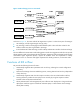
2.
Configure Firewall B
# Configure an IPv4 address for interface GigabitEthernet 0/1.
• Select Device Management > Interface from the navigation tree and then click the icon of
interface GigabitEthernet 0/1.
• Select Static Address for IP Configuration.
• Type IP address 10 .1. 3 .1 .
• Select network mask 24 (255.255.255.0).
• Click Apply.
# Configure an IP address for interface GigabitEthernet 1/1, the physical interface of the tunnel.
• Click the icon of interface GigabitEthernet 1/1.
• Select Static Address for IP Configuration.
• Type IP address 2.2.2.2.
• Select network mask 24 (255.255.255.0).
• Click Apply.
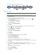
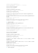
# Create a GRE tunnel.
• Select VPN > GRE from the navigation tree and then click Add.
• Type 0 in the Tunnel Interface text box.
• Type IP address/mask 10.1.2.2/24.
• Select Trust from the Zone drop-down list.
• Type the source end IP address 2.2.2.2, the IP address of GigabitEthernet 1/1.
• Type the destination end IP address 1.1.1.1, the IP address of GigabitEthernet 1/1 on Firewall A.
• Click Apply.
# C
onfigure a static route from Firewall B through interface Tunnel 0 to Group 1.
• Select Network > Routing Management > Static Routing from the navigation tree and then click
Add.
• Type 10.1.1.0 as the destination IP address.
• Select mask 255.255.255.0.
• Select egress interface Tunnel0.
• Click Apply.
Configuring GRE in the CLI
Configuring a GRE over IPv4 tunnel
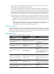
Configuration guidelines
• The source address and destination address of a tunnel uniquely identify a path. They must be
configured at both ends of the tunnel and the source address at one end must be the destination
address at the other end and vice versa.
• Tunnel interfaces using the same encapsulation protocol must have different source addresses and
destination addresses.