HP Load Balancing Module High Availability Configuration Guide Part number: 5998-2687 Document version: 6PW101-20120217
Legal and notice information © Copyright 2012 Hewlett-Packard Development Company, L.P. No part of this documentation may be reproduced or transmitted in any form or by any means without prior written consent of Hewlett-Packard Development Company, L.P. The information contained herein is subject to change without notice.
Contents High availability overview··········································································································································· 1 Availability requirements ·················································································································································· 1 Availability evaluation ········································································································································
Configuring DHCP tests ········································································································································ 56 Configuring DNS tests ·········································································································································· 57 Configuring FTP tests ············································································································································· 58 Configuring HTTP t
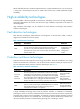
High availability overview Communication interruptions can seriously affect widely-deployed value-added services such as IPTV and video conference. Therefore, the basic network infrastructures must be able to provide high availability.
MTTR = fault detection time + hardware replacement time + system initialization time + link recovery time + routing time + forwarding recovery time. A smaller value of each item, a smaller MTTR and a higher availability. High availability technologies Increasing MTBF or decreasing MTTR can enhance the availability of a network. The high availability technologies described in this section meet the level 3 high availability requirements in the aspect of decreasing MTTR.
VRRP configuration NOTE: • The term router in this document refers to a network device running a routing protocol. • The interfaces that VRRP involves can only be Layer 3 Ethernet interfaces and VLAN interfaces unless otherwise specified. • You cannot configure VRRP on an interface of an aggregation group. • VRRP includes VRRPv2 and VRRPv3. VRRPv2 is based on IPv4, and VRRPv3 is based on IPv6. The web interface supports only IPv4 VRRP configuration.
protocols, route discovery protocols) when a router fails, and prevent network interruption due to failure of a single link. VRRP works in one of the following two modes: • Standard protocol mode—Includes two versions based on RFCs: VRRPv2 and VRRPv3. VRRPv2 is based on IPv4, and VRRPv3 is based on IPv6. The two versions implement the same functions but are applied in different network environments. For more information, see “VRRP standard protocol mode.
NOTE: • A virtual IP address can be either an unused IP address on the segment where the VRRP group resides or the IP address of an interface on a router in the VRRP group. In the latter case, the router is called the IP address owner. • In a VRRP group, you can configure only one IP address owner. • Status of a router in a VRRP group includes master, backup, and initialize. 1. VRRP priority VRRP determines the role (master or backup) of each router in the VRRP group by priority.
You can adjust the interval for sending VRRP advertisements by setting the VRRP advertisement interval timer. If a backup receives no advertisements in a period three times the interval, the backup regards itself as the master and sends VRRP advertisements to start a new master election. 2.
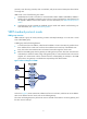
Principles of VRRP 1. Routers in a VRRP group decide their respective roles by priority and IP address. The router with the highest priority becomes the master, and the others are the backups. If the routers have the same priority, the one with the highest IP address becomes the master. The master sends VRRP advertisements periodically to notify the backups that it is working properly, and each of the backups starts a timer to wait for advertisements from the master. 2.
Figure 4 VRRP in master/backup mode At the beginning, Router A is the master and therefore can forward packets to external networks, whereas Router B and Router C are backups and are thus in the state of listening. If Router A fails, Router B and Router C elect for a new master. The new master takes over the forwarding task to provide services to hosts on the LAN. 2.
In Figure 5, three VRRP groups are present: • VRRP group 1—Router A is the master; Router B and Router C are the backups. • VRRP group 2—Router B is the master; Router A and Router C are the backups. • VRRP group 3—Router C is the master; Router A and Router B are the backups. To balance load among Router A, Router B, and Router C, configure hosts on the LAN to use VRRP group 1, 2, and 3 as the default gateways respectively.
Figure 6 Allocating virtual MAC addresses As shown in Figure 6, the virtual IP address of the VRRP group is 10.1.1.1/24; Router A is the master; Router B and Router C are the backups. Router A allocates different virtual MAC addresses to Routers A, B and C. Host A, Host B, and Host C send ARP requests to obtain the MAC address corresponding to the gateway with the virtual IP address 10.1.1.1. The master (Router A) replies ARP requests of the hosts with different virtual MAC addresses.
The priority of a VF decides the VF state. A VF with the highest priority is in the active state and is known as the active virtual forwarder (AVF), which forwards packets; other VFs are in the listening state and are known as the listening virtual forwarders (LVFs), which listen to the state of the AVF. The priority value of a VF ranges from 0 to 255, where 255 is reserved for the VF owner. The priority value of a VF is calculated based on its weight. 2.
Packet Types VRRP standard protocol mode defines only VRRP advertisement. Only the master in a VRRP group sends VRRP advertisements periodically, and the backups do not send VRRP advertisements. To realize load balancing, VRRP load balancing mode defines the following types of packets: • Advertisement—VRRP uses the advertisements to notify the VRRP group state on the local router and the information of the VF that is in the active state.
Figure 8 VRRP interfaces page Figure 9 VRRP group page Figure 10 Create a VRRP group 13
Table 5 VRRP group configuration items Item Description VRID Set the group number of the VRRP group. • Configure the virtual IP address of the VRRP group. • If the VRRP interface connects to multiple subnets, you can configure multiple virtual IP addresses for the VRRP group to implement router backup on different subnets. TIP: • The virtual IP address cannot be all 0s (0.0.0.0), a broadcast address (255.255.255.255), a loopback address, any other invalid IP address (like 0.0.0.
Figure 11 Modify VRRP group Table 7 Configuration items of VRRP group attributes Item Description VRID Display group number of the VRRP group.
Item Description Configure the virtual IP address of the VRRP group. If an interface connects to multiple subnets, you can configure multiple virtual IP addresses for the VRRP group to implement router backup on different subnets. TIP: • The virtual IP address cannot be 0.0.0.0, 255.255.255.255, a loopback address, any other invalid IP address (like 0.0.0.1), or an address that does not belong to class A, B or C.
Item Description Set the authentication mode and plain text authentication key of the VRRP group. Authentication • Null—no authentication and no authentication key. • Simple—simple text authentication. In this case, you need to configure a plain text authentication key. • MD5—MD5 authentication. In this case, you need to configure a plain text authentication key. TIP: Key You can configure different authentication modes and authentication keys for the VRRP groups on an interface.
VRRP configuration examples Single VRRP group configuration example 1. Network requirements As shown in Figure 12: • Host A needs to access Host B on the Internet, using 202.38.160.111/24 as its default gateway. • LB A and LB B belong to VRRP group 1 with the virtual IP address of 202.38.160.111/24. • If LB A operates normally, packets sent from Host A to Host B are forwarded by LB A; if Ten-GigabitEthernet 0/0.
• Type 1 in the VRID box. • Type 202.38.160.111 in the Virtual IP box and then click Add to add the virtual IP address to the Virtual IP Members box. • Click Apply. # Configure VRRP group attributes. • On the VRRP group page of Ten-GigabitEthernet 0/0.1, click the group 1 to enter the page shown in Figure 14. Figure 14 Configure VRRP group attributes • Type 110 in the Priority box. • Select Preemptive from the Preempt Mode box. • Type 5 in the Delay box.
• Select Ten-GigabitEthernet0/0.2 from the Interface box, type 30 in the Reduced Priority box, and then click Add to add the interface to the list box of tracked interface. • Click Apply. 3. Configure LB B # Configure the IP address of each interface and the zones. The configuration is omitted here. # Create VRRP group 1 on Ten-GigabitEthernet 0/0.1 and configure the virtual IP address as 202.38.160.111. • Select High Availability > VRRP from the navigation tree to enter the VRRP interfaces page.
Figure 16 Configure VRRP group attributes • Select Preemptive from the Preempt Mode box. • Type 5 in the Delay box. • Select Simple from the Authentication box. • Type hello in the Key box. • Type 5 in the Advertise Time box. • Click Apply. 4. Verify the configuration After the configuration, Host A can ping Host B. You can view the VRRP group information on Ten -GigabitEthernet 0/0.1 respectively on LB A and LB B. In VRRP group 1, LB A is the master and LB B is the backup router.
Figure 17 Network diagram for multiple VRRP groups configuration Virtual IP address 2: 202.38.160.112/24 Virtual IP address 1: 202.38.160.111/24 Gateway: 202.38.160.111/24 XGE0/0.1 202.38.160.1/24 Host A Gateway: 202.38.160.112/24 Host B LB A Internet XGE0/0.1 202.38.160.2/24 LB B Gateway: 202.38.160.111/24 Host C 2. Configure LB A # Configure the IP address of each interface and the zones. The configuration is omitted here. # Create VRRP group 1 on Ten -GigabitEthernet 0/0.
Figure 19 Create VRRP group 2 • Type 2 in the VRID box. • Type 202.38.160.112 in the Virtual IP box and click Add to add the virtual IP address to the Virtual IP Members box. • Click Apply. # Set the priority of LB A in VRRP group 1 to 110. • On the VRRP group page of Ten-GigabitEthernet 0/0.1, click the group 1 to enter the page shown in Figure 20. icon corresponding to VRRP Figure 20 Set the priority of LB A in VRRP group 1 • Type 110 in the Priority box. • Click Apply. 3.
• Select High Availability > VRRP from the navigation tree to enter the VRRP interfaces page. Click the icon corresponding to Ten-GigabitEthernet 0/0.1, and click Add. • Type 1 in the VRID box. • Type 202.38.160.111 in the Virtual IP box and click Add to add the virtual IP address to the Virtual IP Members box. • Click Apply. # Create VRRP group 2 on Ten-GigabitEthernet 0/0.1 and configure the virtual IP address as 202.38.160.112. • On the VRRP group page of Ten-GigabitEthernet 0/0.1, click Add.
Task Remarks Optional Configuring VF tracking The VF tracking function is effective only when VRRP works in the load balancing mode.
• Load balancing mode—In a VRRP group, all routers (master and backups) that have AVF can forward packets to realize load balancing. After you configure the working mode of a VRRP group, all VRRP groups on the router work in the same mode.
• Specify a single VLAN tag—For subinterfaces configured with ambiguous Dot1q termination, this type of control VLAN should be specified. • Specify both inner and outer VLAN tags—For subinterfaces configured with ambiguous QinQ termination, this type of control VLAN should be specified. Follow these steps to specify the VRRP control VLAN: To do… Use the command… Remarks Enter system view system-view — Layer 3 Ethernet subinterface view interface interface-type interface-number.
NOTE: • When VRRP works in the load balancing mode, the virtual IP address cannot be the same with IP address of any interface in the VRRP group, that is, in the load balancing mode, the VRRP group does not have an IP address owner. • A VRRP group is removed after you remove all the virtual IP addresses in it. In addition, configurations on that VRRP group no longer take effect.
To do… Use the command… Remarks Configure the interface to be tracked vrrp vrid virtual-router-id track interface interface-type interface-number [ reduced priority-reduced ] Optional Configure VRRP to track a specified Track object vrrp vrid virtual-router-id track track-entry-number [ reduced priority-reduced | switchover ] Optional No interface is being tracked by default. Not configured by default.
NOTE: • You can configure the VF tracking function when VRRP works in either the standard protocol mode or the load balancing mode; however, the VF tracking function is effective only when VRRP works in the load balancing mode. • Do not configure VF tracking on an IP address owner. • By default, the weight of a VF is 255, and its lower limit of failure is 10.
Enabling the trap function of VRRP After the trap function is enabled for a VRRP module, the VRRP module will generate traps with severity level errors to report its key events. The generated traps will be sent to the information center of the LB module, where you can configure whether to output the trap information and the output destination. For more information about information center configuration, see System Management Configuration Guide.
Figure 22 Network diagram for single VRRP group configuration Virtual IP address: 202.38.160.111/24 XGE0/0.1 202.38.160.1/24 LB A 203.2.3.1/24 202.38.160.3/24 Internet Host B Host A XGE0/0.1 202.38.160.2/24 LB B 2. Configure LB A system-view [LB A] interface Ten-GigabitEthernet 0/0.1 [LB A-Ten-GigabitEthernet0/0.1] ip address 202.38.160.1 255.255.255.0 # Create VRRP group 1 and configure its virtual IP address as 202.38.160.111. [LB A-Ten-GigabitEthernet0/0.1] vrrp vrid 1 virtual-ip 202.38.
Config Pri : 110 Running Pri : 110 Preempt Mode : Yes Delay Time : 5 Auth Type : None Virtual IP : 202.38.160.111 Virtual MAC : 0000-5e00-0101 Master IP : 202.38.160.1 # Display detailed information of VRRP group 1 on LB B. [LB B-Ten-GigabitEthernet0/0.1] display vrrp verbose IPv4 Standby Information: Run Mode : Standard Run Method : Virtual MAC Total number of virtual routers : 1 Interface Ten-GigabitEthernet0/0.
• If LB A operates normally, packets sent from Host A to Host B are forwarded by LB A; if interface Ten-GigabitEthernet 0/0.1 through which LB A connects to the internet is not available, packets sent from Host A to Host B are forwarded by LB B. Figure 23 Network diagram for interface tracking in VRRP 2. Configure LB A system-view [LB A] interface Ten-GigabitEthernet 0/0.2 [LB A-Ten-GigabitEthernet0/0.2] ip address 202.38.160.1 255.255.255.
[LB B-Ten-GigabitEthernet0/0.2] vrrp vrid 1 timer advertise 5 # Set LB B to work in preemptive mode. The preemption delay is five seconds. [LB B-Ten-GigabitEthernet0/0.2] vrrp vrid 1 preempt-mode timer delay 5 4. Verify the configuration After the configuration, Host B can be pinged through on Host A. You can use the display vrrp verbose command to verify the configuration. # Display detailed information of VRRP group 1 on LB A. [LB A-Ten-GigabitEthernet0/0.
Run Method : Virtual MAC Total number of virtual routers : 1 Interface Ten-GigabitEthernet0/0.2 VRID : 1 Adver Timer : 5 Admin Status : Up State : Backup Config Pri : 110 Running Pri : 80 Preempt Mode : Yes Delay Time : 5 Auth Type : Simple Key : hello Virtual IP : 202.38.160.111 Master IP : 202.38.160.2 VRRP Track Information: Track Interface: XGE0/0.1 State : Down Pri Reduced : 30 # If interface Ten-GigabitEthernet 0/0.
Figure 24 Network diagram for multiple VRRP groups configuration Virtual IP address 2: 202.38.160.112/24 Virtual IP address 1: 202.38.160.111/24 Gateway: 202.38.160.111/24 XGE0/0.1 202.38.160.1/24 Host A LB A Gateway: 202.38.160.112/24 Host B Internet XGE0/0.1 202.38.160.2/24 Gateway: 202.38.160.111/24 LB B Host C 2. Configure LB A system-view [LB A] interface Ten-GigabitEthernet 0/0.1 [LB A-Ten-GigabitEthernet0/0.1] ip address 202.38.160.1 255.255.255.
Total number of virtual routers : 2 Interface Ten-GigabitEthernet0/0.1 VRID : 1 Adver Timer : 1 Admin Status : Up State : Master Config Pri : 110 Running Pri : 110 Preempt Mode : Yes Delay Time : 0 Auth Type : None Virtual IP : 202.38.160.111 Virtual MAC : 0000-5e00-0101 Master IP : 202.38.160.1 Interface Ten-GigabitEthernet0/0.
• LB A, LB B, and Router C belong to VRRP group 1 with the virtual IP address of 10.1.1.1/24. • Hosts on network segment 10.1.1.0/24 use 10.1.1.1/24 as their default gateway. Use the VRRP group to ensure that when a gateway (LB A, LB B, or LB C) fails, the hosts on the LAN can access the external network through another gateway. • VRRP group 1 works in the load balancing mode to make good use of network resources. Figure 25 Network diagram for VRRP load balancing mode 2.
[LB B-Ten-GigabitEthernet0/0.1] ip address 10.1.1.3 24 [LB B-Ten-GigabitEthernet0/0.1] vrrp vrid 1 virtual-ip 10.1.1.1 # Set the priority of LB B in VRRP group 1 to 110. [LB B-Ten-GigabitEthernet0/0.1] vrrp vrid 1 priority 110 # Set LB B to work in preemptive mode. The preemption delay is five seconds. [LB B-Ten-GigabitEthernet0/0.1] vrrp vrid 1 preempt-mode timer delay 5 4. Configure LB C # Configure VRRP to work in the load balancing mode.
Owner ID : 0000-5e01-1103 Priority : 127 Active : 10.1.1.3 Forwarder 03 State : Listening Virtual MAC : 000f-e2ff-0013 (Learnt) Owner ID : 0000-5e01-1105 Priority : 127 Active : 10.1.1.4 # Display detailed information of VRRP group 1 on LB B. [LB B-Ten-GigabitEthernet0/0.1] display vrrp verbose IPv4 Standby Information: Run Mode : Load Balance Run Method : Virtual MAC Total number of virtual routers : 1 Interface Ten-GigabitEthernet0/0.
Run Method : Virtual MAC Total number of virtual routers : 1 Interface Ten-GigabitEthernet0/0.1 VRID : 1 Adver Timer : 1 Admin Status : Up State : Backup Config Pri : 100 Running Pri : 100 Preempt Mode : Yes Delay Time : 5 Auth Type : None Virtual IP : 10.1.1.1 Master IP : 10.1.1.
Forwarder Information: 3 Forwarders 2 Active Config Weight : 255 Running Weight : 255 Forwarder 01 State : Active Virtual MAC : 000f-e2ff-0011 (Take Over) Owner ID : 0000-5e01-1101 Priority : 85 Active : local Redirect Time : 577 secs Time-out Time : 1777 secs Forwarder 02 State : Listening Virtual MAC : 000f-e2ff-0012 (Learnt) Owner ID : 0000-5e01-1103 Priority : 85 Active : 10.1.1.
• Multiple masters coexist for a long period: This is because LB modules in the VRRP group cannot receive VRRP packets, or the received VRRP packets are illegal. Solution: Ping between these masters, and do the following: • If the ping fails, check network connectivity. • If the ping succeeds, check that their configurations are consistent in terms of number of virtual IP addresses, virtual IP addresses, advertisement interval, and authentication. Symptom 3 Frequent VRRP state transition.
Stateful failover configuration NOTE: The LB module supports configuring stateful failover only in the web interface. Overview Introduction to stateful failover Some customers require the key entries or access points of their networks, such as the Internet access point of an enterprise or a database server of a bank, to be highly reliable to ensure continuous data transmission.
NOTE: • The failover link transmits only state negotiation messages and backup data. • Stateful failover can be configured only on management Ethernet interfaces. Figure 27 Network diagram for stateful failover Internet XGE0/0.1 XGE0/0.1 GE0/2 LB A GE0/2 LB B Backup Link XGE0/0.2 XGE0/0.
Configuring stateful failover Select High Availability > Stateful Failover from the navigation tree to enter the stateful failover configuration page, as shown in Figure 29. The upper part of the page allows you to configure stateful failover parameters. The lower part of the page displays the current stateful failover configuration and the failover interface information.
Stateful failover configuration example Network requirements In Figure 27, LB A and LB B are deployed for stateful failover in an enterprise network to provide Internet access. They both run NAT to provide IP address translation. Configure the devices to back up each other, so that when one device fails, the other device takes over the services to ensure service continuity. Configuration procedure 1. Configure LB A. # Configure stateful failover.
Figure 31 Configure stateful failover 2. Configure LB B. The configuration on LB B is omitted because it is similar to that on LB A. Configuration guidelines 1. You must configure VRRP or dynamic routing protocols on the devices and the uplink/downlink devices to ensure that the traffic can automatically switch to the other device if one device fails. 2. Only two stateful failover devices are supported. 3. The same failover interfaces—with the same type and number—must exist on the two devices.
NQA configuration NOTE: The NQA feature can be configured only at CLI. NQA overview Network Quality Analyzer (NQA) can perform various types of tests and collect network performance and service quality parameters such as delay jitter, time for establishing a TCP connection, time for establishing an FTP connection, and file transfer rate. With the NQA test results, you can diagnose and locate network faults, be aware of network performance in time and take proper actions to correct any problems.
• A detection module monitors specific objects, such as the link status, and network performance, and informs the track module of detection results. • Upon the detection results, the track module changes the status of the track entry and informs the associated application module. The track module works between the application modules and the detection modules. It hides the differences among detection modules from application modules.
NOTE: NQA DNS tests do not support the action of sending trap messages. The action to be triggered in DNS tests can only be the default one, none. 4. Reaction entry In a reaction entry, a monitored element, a threshold type, and the action to be triggered are configured to implement threshold monitoring. The state of a reaction entry can be invalid, over-threshold, or below-threshold. Before an NQA test group starts, the reaction entry is in the state of invalid.
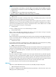
Figure 33 Relationship between the NQA client and NQA server Not all test types require the NQA server. Only the TCP, UDP echo, or UDP jitter test requires both the NQA client and server, as shown in Figure 33. You can create multiple TCP or UDP listening services on the NQA server. Each listens to a specific destination address and port number. Make sure the destination IP address and port number for a listening service on the server are the same as those configured for the test group on the NQA client.
Task Remarks Configuring SNMP tests Configuring TCP tests Configuring UDP echo tests Configuring DLSw tests Configuring the collaboration function Optional Configuring threshold monitoring Optional Configuring the NQA statistics collection function Optional Configuring the history records saving function Optional Configuring optional parameters for an NQA test group Optional Configuring a schedule for an NQA test group Required Configuring the NQA server To perform TCP, UDP echo, or UDP jitter
Creating an NQA test group Create an NQA test group before you configure NQA tests. Follow theses steps to create an NQA test group: To do… Use the command… Remarks Enter system view system-view — Create an NQA test group and enter the NQA test group view Required nqa entry admin-name operation-tag In the NQA test group view, you can specify the test type You can use the nqa entry command to enter the test type view of an NQA test group with test type configured.
To do… Configure the source interface for ICMP echo requests. The requests take the IP address of the source interface as their source IP address when no source IP address is specified. Use the command… Remarks Optional source interface interface-type interface-number By default, no source interface is configured for probe packets. The specified source interface must be up; otherwise, no ICMP echo requests can be sent out. Optional By default, no source IP address is configured.
To do… Use the command… Remarks Required Specify an interface to perform DHCP tests operation interface interface-type interface-number Configure optional parameters See “Configuring optional parameters for an NQA test group” By default, no interface is configured to perform DHCP tests. The specified interface must be up; otherwise, no probe packets can be sent out. Optional NOTE: • The interface that performs DHCP tests does not change its IP address.
Configuring FTP tests FTP tests of an NQA test group are used to test the connection between the NQA client and an FTP server and the time required for the FTP client to transfer a file to or download a file from the FTP server. Configuration prerequisites Before you start FTP tests, configure the FTP server. For example, configure a username and password that are used to log in to the FTP server. For more information about FTP server configuration, see System Maintenance Configuration Guide.
NOTE: • When you execute the put command, a file file-name with fixed size and content is created on the FTP server. When you execute the get command, the device does not save the files obtained from the FTP server. • When you download a file that does not exist on the FTP server, FTP tests fail. • When you execute the get command, use a file with a small size. A big file may result in test failure due to timeout, or may affect other services for occupying too much network bandwidth.
NOTE: The TCP port must be port 80 on the HTTP server for NQA HTTP tests. Configuring UDP jitter tests NOTE: Do not perform NQA UDP jitter tests on known ports, ports from 1 to 1023. Otherwise, UDP jitter tests might fail or the corresponding services of this port might be unavailable. Real-time services such as multimedia have high requirements on delay jitters. UDP jitter tests of an NQA test group obtain uni/bi-directional delay jitters.
To do… Use the command… Specify the source port number of UDP packets source port port-number Configure the size of the data field in each UDP packet data-size size Configure the string to be filled in the data field of each probe packet Remarks Optional By default, no source port number is specified. Optional 100 bytes by default. Optional data-fill string By default, the string is the hexadecimal number 00010203040506070809. probe packet-number Optional packet-number 10 by default.
To do… Use the command… Remarks Enter system view system-view — Enter NQA test group view nqa entry admin-name operation-tag — Configure the test type as SNMP and enter test type view type snmp Required Configure the destination address of SNMP packets destination ip ip-address Specify the source port of SNMP packets source port port-number Required By default, no destination IP address is configured. Optional By default, no source port number is specified.
To do… Use the command… Remarks Required Configure the destination port of TCP probe packets By default, no destination port number is configured. destination port port-number The destination port number must be the same as that of the listening service on the NQA server. Optional Configure the source IP address of TCP probe packets source ip ip-address By default, no source IP address is specified.
To do… Use the command… Configure the size of the data field in each UDP packet data-size size Configure the string to be filled in the data field of each UDP packet data-fill string Specify the source port of UDP packets source port port-number Remarks Optional 100 bytes by default. Optional By default, the string is the hexadecimal number 00010203040506070809. Optional By default, no source port number is specified. Optional By default, no source IP address is specified.
Configuring the collaboration function Collaboration is implemented by establishing reaction entries to monitor the detection results of a test group. If the number of consecutive probe failures reaches the threshold, the configured action is triggered.
To do… Use the command… Remarks Required Configure to send traps to the network management server under specified conditions reaction trap { probe-failure consecutive-probe-failures | test-complete | test-failure cumulate-probe-failures } Configure to send traps. No traps are sent to the network management server by default. NOTE: NQA DNS tests do not support the action of sending trap messages. The action to be triggered in DNS tests can only be the default one, none.
NOTE: • The NQA statistics collection function is not supported in DHCP tests. • If you use the frequency command to set the frequency between two consecutive tests to 0, only one test is performed, and no statistics group information is collected. Configuring the history records saving function The history records saving function enables the system to save the history records of NQA tests. To view the history records of a test group, use the display nqa history command.
To do… Use the command… Remarks Enter NQA test group view nqa entry admin-name operation-tag — Enter test type view of a test group type { dhcp | dlsw | dns | ftp | http | icmp-echo | snmp | tcp | udp-echo | udp-jitter } — Configure the description for a test group Optional description text By default, no description is available for a test group.
Configuration prerequisites Before you configure a schedule for an NQA test group, complete the following tasks: • Configure test parameters required for the test type. • Configure the NQA server for tests that require cooperation with the NQA server.
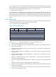
NQA configuration examples ICMP echo test configuration example Network requirements As shown in Figure 34, configure NQA ICMP echo tests to test whether the NQA client (LB module) can send packets through a specified next hop to a specified destination (Device) and test the round-trip time of the packets. Figure 34 Network diagram for ICMP echo tests Configuration procedure NOTE: Before you make the configuration, make sure the devices can reach each other. # Create an ICMP echo test group and specify 10.
Send operation times: 10 Receive response times: 10 Min/Max/Average round trip time: 2/5/3 Square-Sum of round trip time: 96 Last succeeded probe time: 2007-08-23 15:00:01.2 Extended results: Packet lost in test: 0% Failures due to timeout: 0 Failures due to disconnect: 0 Failures due to no connection: 0 Failures due to sequence error: 0 Failures due to internal error: 0 Failures due to other errors: 0 Packet(s) arrived late: 0 # Display the history of ICMP echo tests.
# Enable the saving of history records. [LB-nqa-admin-test-dhcp] history-record enable [LB-nqa-admin-test-dhcp] quit # Start DHCP tests. [LB] nqa schedule admin test start-time now lifetime forever # Stop DHCP tests after a period of time. [LB] undo nqa schedule admin test # Display the results of the last DHCP test.
# Create a DNS test group. system-view [LB] nqa entry admin test [LB-nqa-admin-test] type dns # Specify the IP address of the DNS server 10.2.2.2 as the destination address for DNS tests, and specify the domain name that needs to be translated as host.com. [LB-nqa-admin-test-dns] destination ip 10.2.2.2 [LB-nqa-admin-test-dns] resolve-target host.com # Enable the saving of history records. [LB-nqa-admin-test-dns] history-record enable [LB-nqa-admin-test-dns] quit # Start DNS tests.
Figure 37 Network diagram for FTP tests Configuration procedure NOTE: Before you make the configuration, make sure the devices can reach each other. # Create an FTP test group. system-view [LB] nqa entry admin test [LB-nqa-admin-test] type ftp # Specify the IP address of the FTP server 10.2.2.2 as the destination IP address for FTP tests. [LB-nqa-admin-test-ftp] destination ip 10.2.2.2 # Specify 10.1.1.1 as the source IP address for probe packets. [LB-nqa-admin-test-ftp] source ip 10.1.1.
Failures due to no connection: 0 Failures due to sequence error: 0 Failures due to internal error: 0 Failures due to other errors: 0 Packet(s) arrived late: 0 # Display the history of FTP tests. [LB] display nqa history admin test NQA entry (admin admin, tag test) history record(s): Index Response Status Time 1 173 Succeeded 2007-11-22 10:07:28.
# Start HTTP tests. [LB] nqa schedule admin test start-time now lifetime forever # Stop HTTP tests after a period of time. [LB] undo nqa schedule admin test # Display results of the last HTTP test. [LB] display nqa result admin test NQA entry (admin admin, tag test) test results: Destination IP address: 10.2.2.2 Send operation times: 1 Receive response times: 1 Min/Max/Average round trip time: 64/64/64 Square-Sum of round trip time: 4096 Last succeeded probe time: 2007-11-22 10:12:47.
# Enable the NQA server and configure a listening service to listen to IP address 10.2.2.2 and UDP port 9000. system-view [Device] nqa server enable [Device] nqa server udp-echo 10.2.2.2 9000 2. Configure LB # Create a UDP jitter test group. system-view [LB] nqa entry admin test [LB-nqa-admin-test] type udp-jitter # Configure UDP jitter packets to use 10.2.2.2 as the destination IP address and port 9000 as the destination port. [LB-nqa-admin-test-udp-jitter] destination ip 10.2.2.
Min negative SD: 1 Min negative DS: 6 Max negative SD: 13 Max negative DS: 22 Negative SD number: 4 Negative DS number: 5 Negative SD sum: 38 Negative DS sum: 52 Negative SD average: 10 Negative DS average: 10 Negative SD square sum: 460 Negative DS square sum: 754 One way results: Max SD delay: 15 Max DS delay: 16 Min SD delay: 7 Min DS delay: 7 Number of SD delay: 10 Number of DS delay: 10 Sum of SD delay: 78 Sum of DS delay: 85 Square sum of SD delay: 666 Square sum of DS delay: 787
Max SD delay: 46 Max DS delay: 46 Min SD delay: 7 Min DS delay: 7 Number of SD delay: 410 Number of DS delay: 410 Sum of SD delay: 3705 Sum of DS delay: 3891 Square sum of SD delay: 45987 Square sum of DS delay: 49393 SD lost packet(s): 0 DS lost packet(s): 0 Lost packet(s) for unknown reason: 0 NOTE: The display nqa history command does not show the results of UDP jitter tests.
[LB-nqa-admin-test-snmp] quit # Start SNMP tests. [LB] nqa schedule admin test start-time now lifetime forever # Stop the SNMP tests after a period of time. [LB] undo nqa schedule admin test # Display the results of the last SNMP test. [LB] display nqa result admin test NQA entry (admin admin, tag test) test results: Destination IP address: 10.2.2.
# Enable the NQA server and configure a listening service to listen to IP address 10.2.2.2 and TCP port 9000. system-view [Device] nqa server enable [Device] nqa server tcp-connect 10.2.2.2 9000 2. Configure LB # Create a TCP test group. system-view [LB] nqa entry admin test [LB-nqa-admin-test] type tcp # Configure TCP probe packets to use 10.2.2.2 as the destination IP address and port 9000 as the destination port. [LB-nqa-admin-test-tcp] destination ip 10.2.2.
UDP echo test configuration example Network requirements As shown in Figure 42, configure NQA UDP echo tests to test the round-trip time between LB module and Device. The destination port number is 8000. Figure 42 Network diagram for the UDP echo tests Configuration procedure NOTE: Before you make the configuration, make sure the devices can reach each other. 1. Configure Device # Enable the NQA server and configure a listening service to listen to IP address 10.2.2.2 and UDP port 8000.
Square-Sum of round trip time: 625 Last succeeded probe time: 2007-11-22 10:36:17.9 Extended results: Packet loss in test: 0% Failures due to timeout: 0 Failures due to disconnect: 0 Failures due to no connection: 0 Failures due to sequence error: 0 Failures due to internal error: 0 Failures due to other errors: 0 Packet(s) arrived late: 0 # Display the history of UDP echo tests.
# Display the result of the last DLSw test. [LB] display nqa result admin test NQA entry (admin admin, tag test) test results: Destination IP address: 10.2.2.2 Send operation times: 1 Receive response times: 1 Min/Max/Average round trip time: 19/19/19 Square-Sum of round trip time: 361 Last succeeded probe time: 2007-11-22 10:40:27.
[LB] ip route-static 10.1.1.2 24 10.2.1.1 track 1 3. On LB, create an NQA test group. # Create an NQA test group with the administrator name being admin and operation tag being test. [LB] nqa entry admin test # Configure the test type of the NQA test group as ICMP echo. [LB-nqa-admin-test] type icmp-echo # Configure ICMP echo requests to use 10.2.2.1 as the destination IP address. [LB-nqa-admin-test-icmp-echo] destination ip 10.2.1.
system-view [RouterA] interface ethernet 1/1 [RouterA-Ethernet1/1] undo ip address # On LB, display information about all the track entries. [LB] display track all Track ID: 1 Status: Negative Notification delay: Positive 0, Negative 0 (in seconds) Reference object: NQA entry: admin test Reaction: 1 # Display brief information about active routes in the routing table on LB. [LB] display ip routing-table Routing Tables: Public Destinations : 4 Destination/Mask Proto 10.2.1.
Support and other resources Contacting HP For worldwide technical support information, see the HP support website: http://www.hp.
Conventions This section describes the conventions used in this documentation set. Command conventions Convention Description Boldface Bold text represents commands and keywords that you enter literally as shown. Italic Italic text represents arguments that you replace with actual values. [] Square brackets enclose syntax choices (keywords or arguments) that are optional. { x | y | ... } Braces enclose a set of required syntax choices separated by vertical bars, from which you select one.
Network topology icons Represents a generic network device, such as a router, switch, or firewall. Represents a routing-capable device, such as a router or Layer 3 switch. Represents a generic switch, such as a Layer 2 or Layer 3 switch, or a router that supports Layer 2 forwarding and other Layer 2 features. Represents a LB module. Port numbering in examples The port numbers in this document are for illustration only and might be unavailable on your device.
Index ACDEHNORST A Displaying and maintaining NQA,69 Availability evaluation,1 E Availability requirements,1 Enabling the NQA client,54 C H Configuration guidelines,49 High availability technologies,2 Configuring a schedule for an NQA test group,68 N Configuring an NQA test group,55 NQA configuration examples,70 Configuring optional parameters for an NQA test group,67 NQA configuration task list,53 NQA overview,50 Configuring stateful failover,47 Configuring the collaboration function,65 O