
R3204P16-HP Load Balancing Module High Availability Configuration Guide-6PW101

21
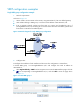
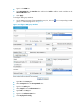
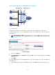
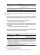
Figure 16 Configure VRRP group attributes
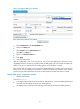
• Select Preemptive from the Preempt Mode box.
• Type 5 in the Delay box.
• Select Simple from the Authentication box.
• Type hello in the Key box.
• Type 5 in the Advertise Time box.
• Click Apply.
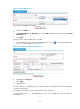
4. Verify the configuration
After the configuration, Host A can ping Host B. You can view the VRRP group information on Ten
-GigabitEthernet 0/0.1 respectively on LB A and LB B. In VRRP group 1, LB A is the master and LB B is the
backup router. LB A is responsible for forwarding packets sent from Host A to Host B.
If the interface that connects LB A to the Internet (Ten -GigabitEthernet 0/0.2) fails, Host A can still ping
Host B. In this case, the VRRP group information shows that LB A becomes a backup router with the
priority being 80 and LB B becomes the master. LB B forwards the packets from Host A to Host B.
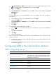
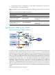
Multiple VRRP groups configuration example
1. Network requirements
As shown in Figure 17:
• I
n t h e s e g m e n t 2 02. 3 8 .16 0 .0 / 2 4 , s o m e h o s t s u s e 2 0 2 . 38 .16 0 .111/24 as their default gateway and
some hosts use 202.38.160.112/24 as their default gateway.
• Use VRRP groups to implement load balancing and mutual backup between default gateways.