
R3204P16-HP Load Balancing Module High Availability Configuration Guide-6PW101

22
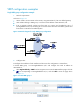
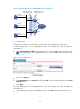
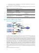
Figure 17 Network diagram for multiple VRRP groups configuration
2.
Configure LB A
# Configure the IP address of each interface and the zones. The configuration is omitted here.
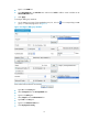
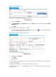
# Create VRRP group 1 on Ten -GigabitEthernet 0/0.1 and configure the virtual IP address as
2 0 2 . 3 8 .16 0 .111.
• Select High Availability > VRRP from the navigation tree to enter the VRRP interfaces page. Click the
icon corresponding to Ten -GigabitEthernet 0/0.1, and click Add to enter the page shown
in Figure 18.
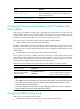
Figure 18 Create VRRP
group 1
• Type 1 in the VRID box.
• Type 202.38.160.111 in the Virtual IP box and click Add to add the virtual IP address to the Virtual
IP Members box.
• Click Apply.
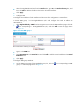
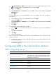
# Create VRRP group 2 on Ten-GigabitEthernet 0/0.1 and configure the virtual IP address as
2 0 2 . 3 8 .16 0 .112.
• On the VRRP group page of Ten-GigabitEthernet 0/0.1, click Add to enter the page shown in Figure
19.
Host A
Host B
Host C
LB A
LB B
Virtual IP address 1:
202.38.160.111/24
Virtual IP address 2:
202.38.160.112/24
XGE0/0.1
202.38.160.1/24
XGE0/0.1
202.38.160.2/24
Gateway:
202.38.160.111/24
Gateway:
202.38.160.112/24
Gateway:
202.38.160.111/24
Internet