
R3204P16-HP Load Balancing Module High Availability Configuration Guide-6PW101

26
• Load balancing mode—In a VRRP group, all routers (master and backups) that have AVF can
forward packets to realize load balancing.
After you configure the working mode of a VRRP group, all VRRP groups on the router work in the same
mode.
Follow these steps to configure the VRRP working mode:
To do… Use the command…
Remarks
Enter system view system-view —
Configure VRRP to work in the
standard protocol mode
undo vrrp mode
Optional
By default, VRRP works in the standard
protocol mode.
Configure VRRP to work in the
load balancing mode
vrrp mode load-balance
Optional
By default, VRRP works in the standard
protocol mode.
Specifying the VRRP control VLAN
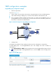
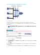
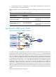
Figure 21 Network diagram for VRRP control VLAN
To realize inter-VLAN or LAN-WAN communication, you need to configure VLAN termination on the
subinterfaces of Layer 3 Ethernet interfaces on routers. As shown in Figure 21, c
onfigure ambiguous
VLAN termination for VLAN 10 and VLAN 20 on the Layer 3 Ethernet subinterfaces on routers. At this
time, if you enable the subinterfaces configured with VLAN termination to transmit broadcast/multicast
packets, the master sends VRRP advertisements within all VLANs whose VLAN packets are configured to
be terminated by the subinterfaces. If the Layer 3 Ethernet subinterfaces are configured to terminate
packets from many VLANs, there will be many VRRP advertisements to be transmitted through the
subinterfaces, and the performance of the router will be seriously affected. If you disable the
subinterfaces configured with VLAN termination from transmitting broadcast/multicast packets, the
master cannot send VRRP advertisements to the backups. To solve this problem, you can configure a
VRRP control VLAN to allow the master to send VRRP advertisements only within the control VLAN when
the subinterfaces configured with VLAN termination are disabled from transmitting broadcast/multicast
packets
VRRP control VLAN falls into two categories: