
R3204P16-HP Load Balancing Module High Availability Configuration Guide-6PW101

32
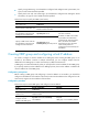
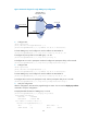
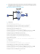
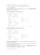
Figure 22 Network diagram for single VRRP group configuration
2. Configure LB A
<LB A> system-view
[LB A] interface Ten-GigabitEthernet 0/0.1
[LB A-Ten-GigabitEthernet0/0.1] ip address 202.38.160.1 255.255.255.0
# Create VRRP group 1 and configure its virtual IP address as 202.38.160.111.
[LB A-Ten-GigabitEthernet0/0.1] vrrp vrid 1 virtual-ip 202.38.160.111
# Configure the priority of LB A in the VRRP group 1 as 110.
[LB A-Ten-GigabitEthernet0/0.1] vrrp vrid 1 priority 110
# Configure LB A to work in preemptive mode and configure the preemption delay as five seconds.
[LB A-Ten-GigabitEthernet0/0.1] vrrp vrid 1 preempt-mode timer delay 5
3. Configure LB B
<LB B> system-view
[LB B] interface Ten-GigabitEthernet 0/0.1
[LB B-Ten-GigabitEthernet0/0.1] ip address 202.38.160.2 255.255.255.0
# Create VRRP group 1 and configure its virtual IP address as 202.38.160.111.
[LB B-Ten-GigabitEthernet0/0.1] vrrp vrid 1 virtual-ip 202.38.160.111
# Configure LB B to work in the preemptive mode, with the preemption delay set to 5 seconds.
[LB B-Ten-GigabitEthernet0/0.1] vrrp vrid 1 preempt-mode timer delay 5
4. Verify the configuration
After the configuration, Host B can be pinged through on Host A. You can use the display vrrp verbose
command to verify the configuration.
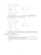
# Display detailed information of VRRP group 1 on LB A.
[LB A-Ten-GigabitEthernet0/0.1] display vrrp verbose
IPv4 Standby Information:
Run Mode : Standard
Run Method : Virtual MAC
Total number of virtual routers : 1
Interface Ten-GigabitEthernet0/0.1
VRID : 1 Adver Timer : 1
Admin Status : Up State : Master
Host A
LB A
LB B
Virtual IP address:
202.38.160.111/24
XGE0/0.1
202.38.160.1/24
XGE0/0.1
202.38.160.2/24
Host B
202.38.160.3/24
203.2.3.1/24
Internet