
R3204P16-HP Load Balancing Module High Availability Configuration Guide-6PW101

39
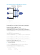
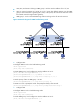
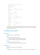
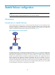
• LB A, LB B, and Router C belong to VRRP group 1 with the virtual IP address of 10.1.1.1/24.
• H o s t s o n n e t w o r k s e g m e n t 10 .1.1. 0 / 2 4 u s e 10 .1.1.1 / 24 a s t h e i r d e f a u l t g a t e w a y. U s e t h e V R R P
group to ensure that when a gateway (LB A, LB B, or LB C) fails, the hosts on the LAN can access
the external network through another gateway.
• VRRP group 1 works in the load balancing mode to make good use of network resources.
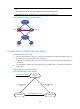
Figure 25 Network diagram for VRRP load balancing mode
2. Configure LB A
# Configure VRRP to work in the load balancing mode.
<LB A> system-view
[LB A] vrrp mode load-balance
# Create VRRP group 1 and configure its virtual IP address as 10.1.1.1.
[LB A] interface Ten-GigabitEthernet 0/0.1
[LB A-Ten-GigabitEthernet0/0.1] ip address 10.1.1.2 24
[LB A-Ten-GigabitEthernet0/0.1] vrrp vrid 1 virtual-ip 10.1.1.1
# Set the priority of LB A in VRRP group 1 to 120.
[LB A-Ten-GigabitEthernet0/0.1] vrrp vrid 1 priority 120
# Set LB A to work in preemptive mode. The preemption delay is five seconds.
[LB A-Ten-GigabitEthernet0/0.1] vrrp vrid 1 preempt-mode timer delay 5
3. Configure LB B
# Configure VRRP to work in load balancing mode.
<LB B> system-view
[LB B] vrrp mode load-balance
# Create VRRP group 1 and configure its virtual IP address as 10.1.1.1.
[LB B] interface Ten-GigabitEthernet 0/0.1