
R3204P16-HP Load Balancing Module High Availability Configuration Guide-6PW101

45
Stateful failover configuration
NOTE:
The LB module supports configuring stateful failover only in the web interface.
Overview
Introduction to stateful failover
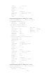
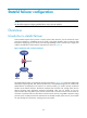
Some customers require the key entries or access points of their networks, such as the Internet access
point of an enterprise or a database server of a bank, to be highly reliable to ensure continuous data
transmission. Deploying only one device (even with high reliability) in such a network risks a single point
of failure and therefore cannot meet the requirement, as shown in Figure 26.
Figure 26 Network with one device deployed
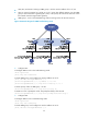
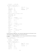
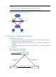
The stateful failover feature is introduced to meet the requirement. In Figure 27, two devices installed with
LB modules (supporting NAT, ALG, blacklist, DHCP server, and load balancing) that are enabled with
stateful failover are deployed in the network. On each LB module, you need to specify an Ethernet
interface as the failover interface. The failover interfaces form a failover link, through which the two
devices exchange state negotiation messages periodically. After the two devices go into the
synchronization state, they back up the services of each other to ensure that the services on them are
consistent. If one device fails, the other device can take over the services using VRRP or dynamic routing
protocols (such as OSPF). Because the other device has already backed up the services, service traffic
can pass through the other device, avoiding service interruption.