
R3204P16-HP Load Balancing Module High Availability Configuration Guide-6PW101

46
NOTE:
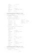
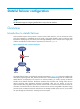
• The failover link transmits only state negotiation messages and backup data.
• Stateful failover can be configured only on management Ethernet interfaces.
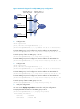
Figure 27 Network diagram for stateful failover
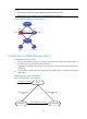
Introduction to stateful failover states
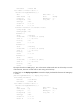
The stateful failover states include:
• Silence: Indicates that the device is just started and waiting for the stable running of the system, or
the state between synchronization and independence.
• Independence: Indicates that the silence timer expires, but no failover link to any other device is
established.
• Synchronization: Indicates that state negotiation with another device is complete and ready for
data backup.
The following figure shows state relations.
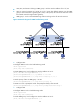
Figure 28 Stateful failover state diagram
Internet
内网
LB A
Host A Host B
Backup Link
GE0/2 GE0/2
XGE0/0.1 XGE0/0.1
XGE0/0.2
XGE0/0.2
LB B
Intranet
Silence
The device is started
Independence
The silence timer
expires
Synchronization
State negotiation succeeds
State negotiation
fails