
R3204P16-HP Load Balancing Module High Availability Configuration Guide-6PW101

49
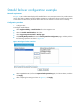
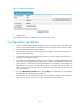
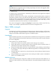
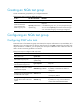
Figure 31 Configure stateful failover
2. Configure LB B.
The configuration on LB B is omitted because it is similar to that on LB A.
Configuration guidelines
1. You must configure VRRP or dynamic routing protocols on the devices and the uplink/downlink
devices to ensure that the traffic can automatically switch to the other device if one device fails.
2. Only two stateful failover devices are supported.
3. The same failover interfaces—with the same type and number—must exist on the two devices.
Otherwise, data backup fails.
4. If an Ethernet interface is the current failover interface, you cannot configure other functions or
parameters on the Ethernet interface.
5. To run NAT on two stateful failover devices, you must configure two identical NAT address pools
for each device, but the higher-priority address pool on a device must be different from that on the
other; otherwise, a conflict may occur during stateful failover. For example, you can configure two
NAT address pools, 100.0.0.1 through 100.0.0.5 (Pool 1), and 100.0.0.6 through 100.0.0.10
(Pool 2) on devices A and B. Pool 1 has a lower priority on Device A, while Pool 2 has a lower
priority on Device B.
6. If you click Modify Backup Interface before clicking Apply, the configurations you have made on
the stateful failover configuration page will be lost.
7. Use a network cable or optical fiber to directly connect the failover interfaces. No intermediary
device (such as a router, a switch, or a hub) is allowed between the interfaces.