
R3204P16-HP Load Balancing Module High Availability Configuration Guide-6PW101

3
VRRP configuration
NOTE:
• The term
router
in this document refers to a network device running a routing protocol.
• The interfaces that VRRP involves can only be Layer 3 Ethernet interfaces and VLAN interfaces unless
otherwise specified.
• You cannot configure VRRP on an interface of an aggregation group.
• VRRP includes VRRPv2 and VRRPv3. VRRPv2 is based on IPv4, and VRRPv3 is based on IPv6. The web
interface supports only IPv4 VRRP configuration.
Overview
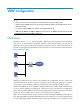
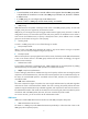
Typically, as shown in Figure 1, you can configure a default route with the gateway as the next hop for
every host on a network segment. All packets destined to other network segments are sent over the
default route to the gateway and then forwarded by the gateway. However, when the gateway fails, all
the hosts using the gateway as the default next-hop router fail to communicate with the external network.
Figure 1 LAN networking
Configuring a default route for network hosts facilitates your configuration, but also requires high
performance stability of the device acting as the gateway. Using more egress gateways is a common
way to improve system reliability, introducing the problem of routing among the multiple egresses.
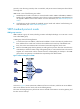
Virtual Router Redundancy Protocol (VRRP) is designed to address this problem. VRRP adds routers that
can act as network gateways to a VRRP group, which forms a virtual router. Routers in the VRRP group
elect a master through the VRRP election mechanism to take the responsibility of a gateway, and hosts on
a LAN only need to configure the virtual router as their default network gateway.
VRRP is an error-tolerant protocol, which improves the network reliability and simplifies configurations on
hosts. Deploying VRRP on multicast and broadcast LANs such as Ethernet, you can ensure that the system
can still provide highly reliable default links without changing configurations (such as dynamic routing