HP Load Balancing Module Load Balancing Configuration Guide Part number: 5998-2685 Document version: 6PW101-20120217
Legal and notice information © Copyright 2012 Hewlett-Packard Development Company, L.P. No part of this documentation may be reproduced or transmitted in any form or by any means without prior written consent of Hewlett-Packard Development Company, L.P. The information contained herein is subject to change without notice.
Contents Load balancing configuration ····································································································································· 1 Load balancing overview ················································································································································· 1 Classification of LB ·················································································································································
Load balancing configuration NOTE: The SecBlade LB module supports configuring IPv4 server load balancing and firewall load balancing only in the web interface. Load balancing overview Load balancing (referred to as LB hereinafter) is a cluster technology to distribute some specific services such as network services and network traffic among multiple network devices (for example servers and firewalls), enhancing service processing capability and ensuring high reliability of services.
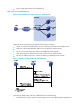
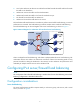
• Direct routing (DR)-mode server load balancing NAT-mode server load balancing Figure 1 Network diagram for NAT-mode server load balancing NAT-mode server load balancing includes the following basic elements: • Cluster: A cluster that provides specific services, including an LB device and multiple servers. • LB device: A device that distributes different service requests to multiple servers. • Server: A server that responds to and processes different service requests.
2. Upon receiving the request, the LB device uses an algorithm to calculate to which server it distributes the request. 3. The LB device uses the Destination NAT (DNAT) technology to distribute the request, with the host IP being the source IP and Server IP being the destination IP. 4. The server receives and processes the request and then sends a response, with the server IP being the source IP, and the host IP being the destination IP. 5.
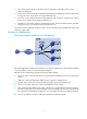
Figure 4 Work flow of DR-mode server load balancing The following describes the work flow of DR-mode server load balancing: 1. The host sends a request, with VSIP being the destination address. 2. Upon receiving the request, the general device forwards it to LB device. Note that the VSIP cannot be contained in an ARP request and response; therefore the general device only forwards the request to the LB device. 3.
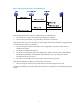
Working mechanism of firewall load balancing Figure 5 Network diagram for firewall load balancing Firewall load balancing includes the following basic elements: • Cluster: A cluster consists of LB devices and firewalls to provide network traffic load balancing. • LB device: A device that distributes traffic from the request sender to multiple firewalls. LB devices fall into level 1 LB devices and level 2 LB devices.
4. As a level 2 LB device, LB device B records the firewall that forwards the traffic and then forwards the traffic to the destination. 5. LB device B receives the traffic sent from the destination. 6. LB device B forwards the traffic to the firewall recorded in step 4. 7. The firewall forwards the traffic to LB device A. 8. LB device A forwards the traffic back to the source.
Figure 8 Relationship between the components of the server load balancing module • Real service group: A group of real services. • Real services: Entities that process services in a cluster (such as servers in Figure 1, and Figure 3, and firewalls Figure 5. • Virtual service: A logical entity that faces users. A virtual service can correspond to multiple real services.
Task Remarks Required Creating a virtual service Allows you to create a virtual service and reference the related real service group. By default, no virtual service exists in the system. Optional Displaying server load balancing statistics Optional Optional Enabling stopping service or slow-offline To remove the server or network device corresponding to a real service from a cluster, you can enable slow-offline for the real service.
Item Description Set whether to enable unidirectional traffic detection. Enable unidirectional traffic detection A unidirectional traffic indicates that only packets in one direction pass the device for one session. In this case, the state machine of the device cannot process the packets. After unidirectional traffic detection is enabled, a special state machine will be used to process both bidirectional and unidirectional traffic.
Table 3 Real service group configuration items Item Description Real Service Group Name Set a real service group name, which uniquely identifies a real service group. Select an algorithm that a real service group uses to distribute services and traffic: • Round Robin: Assigns new connections to each real service in turn. • Weighted Round Robin: Assigns new connections to real services based on the weights of real services; a higher weight indicates more new connections will be assigned.
Item Description Select a health monitoring method that a real service group uses to monitor a real service: • TCP: Monitors the availability of an application port by establishing TCP connections. • ICMP: Monitors the reachability of a server by sending ICMP packets. • HTTP: Monitors the availability of an HTTP service through HTTP access. Health Monitoring Type • FTP: Monitors the availability of an FTP server through FTP. • DNS: Monitors the availability of a DNS server through DNS.
Creating a real service Select Load Balance > Server Load Balancing from the navigation tree, and then click the Real Service tab to enter the page as shown in Figure 12. Click Add to enter the real service group configuration page, as shown in Figure 13. Figure 12 Real service Figure 13 Create a real service Table 4 Real service configuration items Item Description Real Service Name Set a real service name, which uniquely identifies a real service.
Item Description Set a port number that is related to the following parameters: • Health monitoring method for a service group: If the health monitoring type is TCP, then the port number is used for TCP health monitoring. Port • Forwarding mode for a virtual service: If the forwarding mode is set to Weight Set the weight to be used in the weighted round robin and weighted least connections algorithms.
Figure 14 Modify real service • To enable slow-offline of a real service, select the Enable Slow-Offline option, and then click Apply. After slow-offline is enabled, you can view the server load balancing statistics, and then remove the corresponding server or network device from the cluster after the original services of the real service are processed. After slow-offline is enabled, the status LED of the real service changes from .
Figure 15 Virtual service Figure 16 Create a virtual service Table 5 Virtual service configuration items Item Description Virtual Service Name Set a virtual service name, which uniquely identifies a virtual service. VPN Instance Select the VPN instance to which the virtual service belongs. Virtual Service IP Mask Specifies the VSIP and VSIP mask of the cluster, used for requesting services. Protocol Select the protocol used by the cluster to provide services.
Item Description Load balancing mode adopted: Forwarding Mode • NAT: NAT-mode server load balancing • Direct Routing: DR-mode server load balancing • Firewall: firewall load balancing Enable source address NAT translation, which changes the source address of a packet during load balancing. It can be set only when the forwarding mode is NAT.
rate/peak rate, number of forwarded/ignored packets in the inbound direction, and number of forwarded packets in the outbound direction. If you click the link of a virtual service name, the statistics of all the real services of the virtual service will be displayed on the lower part of the page, including total number of connections, average of active connections/peak of active connections, connection average rate/peak rate, packets received, and packets sent, as shown in Figure 17.
Figure 19 Modify health monitoring parameters Table 6 Configuration items for setting health monitoring parameters Item Remarks Health Monitoring A method to be used in health monitoring Check Interval The interval at which health monitoring is performed.
Item Remarks Username Username and password for logging in to the RADIUS server in RADIUS health monitoring, case sensitive. Password Authentication Server Shared Key RADIUS Packet Source IP The default username is admin. Shared key for RADIUS authentication packets in RADIUS health monitoring The default authentication server shared key is 0123456789.
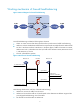
• All traffic will pass the firewall: NAT-mode server load balancing (Responses in DR mode do not pass the firewall). • The performance of the three servers is different and therefore weighted round robin algorithm is adopted. Figure 20 Network diagram for NAT-mode server load balancing Configuration procedure NOTE: • Assume that Server A, Server B, and Server C have been configured (including routing information that ensures normal packet forwarding).
• Type the real service group name HTTPGroup. • Select the algorithm Weighted Round Robin. • Select the health monitoring type ICMP. • Select the troubleshooting method Keep Connected. • Click Apply. # Create real service ServerA for Server A. • Click the Real Service tab, and click Add to perform the following configurations, as shown in Figure 22. Figure 22 Create a real service • Type the real service name ServerA. • Type the IP address of the real service 192.168.1.1.
• Type the IP address of the real service 192.168.1.3. • Type the port number 8080. • Type the weight 100. • Select the real service group HTTPGroup. • Click Apply. # Create virtual service VS. • Click Virtual Service, and click Add to perform the following configurations, as shown in Figure 23. Figure 23 Create virtual service VS • Type the virtual service name VS. • Type the IP address of the virtual service 61.159.4.100. • Select the mask 32 (255.255.255.255).
• Select Load Balance > Server Load Balance from the navigation tree, and click the Statistics tab. • Click the virtual service name link of virtual service VS, and you can see the statistics on the corresponding page, as shown in Figure 24. Figure 24 Statistics From Figure 24, you can see that the total number of connections of Server A, Server B and Server C is in a ratio of 15:12:10, which is the same as that of the configured weights. Therefore, the server load balancing function has taken effect.
Figure 25 Network diagram for firewall load balancing Configuration procedure NOTE: • Assume that Firewall A and Firewall B have been configured (including routing information that ensures normal packet forwarding). • Assume that the IP addresses of the interfaces on the LB devices and the zones to which they belong have been configured. The following describes the configurations of load balancing in detail. # Enable the function of keeping the last hop information on LB device B.
Figure 27 Create a real service group • Type the real service group name FirewallGroup. • Select the algorithm Destination IP Hashing. • Select the health monitoring type ICMP. • Select the troubleshooting method Redirection. • Click Apply. # Create real service FirewallA for Firewall A on LB device A. • Click the Real Service tab, and click Add to perform the following configuration, as shown in Figure 28. Figure 28 Create a real service • Type the real service name FirewallA.
• Click Add on the Real Service tab to perform the following configuration, as shown in Figure 28. • Type the real service name FirewallB. • Type the IP address of the real service 10.0.1.2. • Select the real service group FirewallGroup. • Click Apply. # Create virtual service VS on LB device A. • Click Virtual Service, and click Add to perform the following configuration, as shown in Figure 29. Figure 29 Create virtual service VS • Type the virtual service name VS.
• Click the virtual service name link of virtual service VS, and you can see the statistics on the corresponding page, as shown in Figure 30. Figure 30 Statistics on LB device A From Figure 30, you can see that the traffic from the internal network to the Internet is balanced by Firewall A and Firewall B.
Support and other resources Contacting HP For worldwide technical support information, see the HP support website: http://www.hp.
Conventions This section describes the conventions used in this documentation set. Command conventions Convention Description Boldface Bold text represents commands and keywords that you enter literally as shown. Italic Italic text represents arguments that you replace with actual values. [] Square brackets enclose syntax choices (keywords or arguments) that are optional. { x | y | ... } Braces enclose a set of required syntax choices separated by vertical bars, from which you select one.
Network topology icons Represents a generic network device, such as a router, switch, or firewall. Represents a routing-capable device, such as a router or Layer 3 switch. Represents a generic switch, such as a Layer 2 or Layer 3 switch, or a router that supports Layer 2 forwarding and other Layer 2 features. Represents a LB module. Port numbering in examples The port numbers in this document are for illustration only and might be unavailable on your device.
Index CLR Load balancing configuration examples,19 C Load balancing overview,1 Configuring IPv4 server/firewall load balancing,6 Contacting HP,28 R Conventions,29 Related information,28 L 31