
R3204P16-HP Load Balancing Module Load Balancing Configuration Guide-6PW101

20
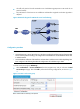
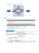
• All traffic will pass the firewall: NAT-mode server load balancing (Responses in DR mode do not
pass the firewall).
• The performance of the three servers is different and therefore weighted round robin algorithm is
adopted.
Figure 20 Network diagram for NAT-mode server load balancing
Configuration procedure
NOTE:
• Assume that Server A, Server B, and Server C have been configured (including routing information tha
t
ensures normal packet forwarding). The configurations of the HTTP server are omitted here. Please refer
to related manuals.
• Assume that the IP addresses of the interfaces on the LB device and the zones to which they belong have
been configured. The following describes the configurations of load balancing in detail.
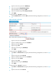
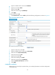
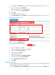
# Create a real service group HTTPGroup.
• Select Load Balance > Server Load Balance from the navigation tree, and you will enter the Real
Service Group tab page. Then click Add to perform the following configurations, as shown in Figure
21.
Figure 21 Create a real
service group