
R3204P16-HP Load Balancing Module Load Balancing Configuration Guide-6PW101

23
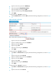
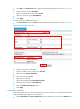
• Select Load Balance > Server Load Balance from the navigation tree, and click the Statistics tab.
• Click the virtual service name link of virtual service VS, and you can see the statistics on the
corresponding page, as shown in Figure 24.
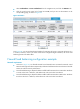
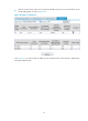
Figure 24 Statistics
From Figure 24, you can see that the total number of connections of Server A, Server B and Server C is
in a ratio of 15:12:10, which is the same as that of the configured weights. Therefore, the server load
balancing function has taken effect.
Firewall load balancing configuration example
Network requirements
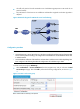
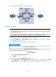
• As shown in Figure 25, two firewalls Firewall A and Firewall B are connected to Network A and
Network B through an LB device respectively to balance load between the internal network and the
Internet to enhance network performance.
• Firewall load balancing is adopted to balance traffic load from Network A to Network B. LB device
A works as the level 1 LB device, and LB device B works as the level 2 LB device.
• Firewall load balancing is adopted to balance traffic load from Network B to Network A. LB device
B works as the level 1 LB device, and LB device A works as the level 2 LB device