
R3204P16-HP Load Balancing Module Load Balancing Configuration Guide-6PW101

24
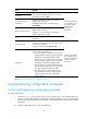
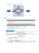
Figure 25 Network diagram for firewall load balancing
Configuration procedure
NOTE:
• Assume that Firewall A and Firewall B have been configured (including routing information that ensures
normal packet forwarding).
• Assume that the IP addresses of the interfaces on the LB devices and the zones to which they belong have
been configured. The following describes the configurations of load balancing in detail.
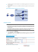
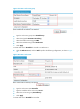
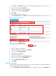
# Enable the function of keeping the last hop information on LB device B.
• Select Load Balance > Global Setting from the navigation tree to perform the following
configuration, as shown in Figure 26.
Figure 26 Enable the fu
nction of keeping the last hop information
• Select the Keep Last-hop Information option.
• Click Apply.
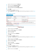
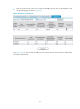
# Create real service group FirewallGroup on LB device A.
• Select Load Balance > Server Load Balance from the navigation tree, and you will enter the Real
Service Group tab. Then click Add to perform the following configuration, as shown in Figure 27.