
R3204P16-HP Load Balancing Module Load Balancing Configuration Guide-6PW101

3
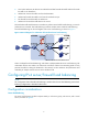
2.
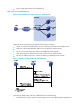
Upon receiving the request, the LB device uses an algorithm to calculate to which server it
distributes the request.
3. The LB device uses the Destination NAT (DNAT) technology to distribute the request, with the host
IP being the source IP and Server IP being the destination IP.
4. The server receives and processes the request and then sends a response, with the server IP being
the source IP, and the host IP being the destination IP.
5. The LB device receives the response, translates the source IP, and forwards the response, with VSIP
being the source IP, and the host IP being the destination IP.
The above work flow indicates that NAT is used in server load balancing, and NAT-mode server load
balancing is thus called.
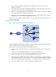
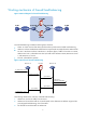
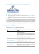
DR-mode server load balancing
Figure 3 Network diagram for DR-mode server load balancing
DR mode is different from NAT mode in that NAT is not used in load balancing. This means that besides
its local IP address, a server must have the VSIP configured.
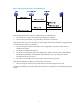
DR-mode server load balancing includes the following basic elements:
• Cluster: A cluster consists of an LB device, a general device and multiple servers to provide specific
services.
• LB device: A device that distributes different service requests to multiple servers.
• General device: A device that forwards data according to general forwarding rules.
• Server: A server that responds to and processes different service requests.
• VSIP: Virtual service IP address of the cluster, used for users to request services. Besides configuring
the VSIP on the LB device, you need to configure it on servers (Because the VSIP on the server cannot
be contained in an ARP request and response, you can configure the VSIP on a loopback interface).
• Server IP: IP address of a server, used by the LB device to distribute requests.