
R3204P16-HP Load Balancing Module Load Balancing Configuration Guide-6PW101

4
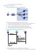
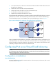
Figure 4 Work flow of DR-mode server load balancing
The following describes the work flow of DR-mode server load balancing:
1. The host sends a request, with VSIP being the destination address.
2. Upon receiving the request, the general device forwards it to LB device.
Note that the VSIP cannot be contained in an ARP request and response; therefore the general device
only forwards the request to the LB device.
3. Upon receiving the request, the LB device uses an algorithm to calculate to which server it
distributes the request.
4. The LB device distributes the request.
5. The LB device encapsulates VSIP as the destination IP address, and the server’s MAC address
(obtained through ARP) as the destination MAC address. In this way, the request can be
forwarded normally to the server.
6. The server receives and processes the request, and then sends a response.
Note that the destination IP address of the response is the host IP.
7. After receiving the response, the general device forwards the response to the host.
The response is addressed to the host rather than the LB device, so DR-mode server load balancing is thus
called.