
R3204P16-HP Load Balancing Module Load Balancing Configuration Guide-6PW101

6
4.
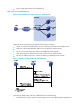
As a level 2 LB device, LB device B records the firewall that forwards the traffic and then forwards
the traffic to the destination.
5. LB device B receives the traffic sent from the destination.
6. LB device B forwards the traffic to the firewall recorded in step 4.
7. The firewall forwards the traffic to LB device A.
8. LB device A forwards the traffic back to the source.
The load balanced firewalls between two LB devices perform network traffic load balancing, so network
performance is increased. This load balancing mode has another name: sandwich load balancing.
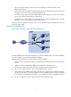
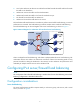
Firewall load balancing can be used together with server load balancing, as shown in Figure 7.
Figure 7 Network diagram for combi
nation of firewall and server load balancing
Cluster A adopts firewall load balancing, and Cluster B adopts NAT-mode server load balancing. The
combination of these two modes is to combine the work flows of them. This networking mode not only
prevents firewalls from being the bottleneck in the network, but also enhances the performance and
availability of multiple network services such as HTTP and FTP.
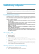
Configuring IPv4 server/firewall load balancing
NOTE:
The configuration of IPv4 firewall load balancin
g
is similar to that of server load balancin
g
. Server load
balancing configuration is described in this section.
Configuration considerations
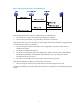
Server load balancing
The server load balancing module comprises mainly a real service group, real services, and a virtual
service, as shown in Figure 8.