HP Load Balancing Module Network Management Configuration Guide Part number: 5998-2684 Document version: 6PW101-20120217
Legal and notice information © Copyright 2012 Hewlett-Packard Development Company, L.P. No part of this documentation may be reproduced or transmitted in any form or by any means without prior written consent of Hewlett-Packard Development Company, L.P. The information contained herein is subject to change without notice.
Contents Interface management configuration ·························································································································· 1 Interface overview ····························································································································································· 1 Managing interfaces in the web ·····································································································································
Displaying and maintaining inter-VLAN Layer 2 forwarding ··········································································· 33 Forward-type inline Layer 2 forwarding configuration example··············································································· 34 Blackhole-type inline Layer 2 forwarding configuration example ············································································ 34 Inter-VLAN Layer 2 forwarding configuration example ······································
Displaying and maintaining Layer 3 subinterface forwarding ········································································· 74 Configuring inter-VLAN Layer 3 forwarding ··············································································································· 74 Configuring inter-VLAN Layer 3 forwarding ······································································································ 74 Displaying and maintaining inter-VLAN Layer 3 forwarding ··············
Configuration overview ··············································································································································· 124 Configuring OSPF globally ········································································································································· 125 Configuring OSPF areas ············································································································································· 125 Conf
Index ········································································································································································ 171 v
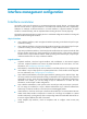
Interface management configuration Interface overview An interface is the point of interaction or communication between network devices. It exchanges data between network devices. A physical interface is an interface that materially exists and is supported by hardware. For example, an Ethernet interface or a console interface is a physical interface. A logical interface is created manually, and can implement data switching but does not exist physically.
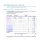
Managing interfaces in the web You can use the interface management feature to view interface information, create or remove logical interfaces, change interface status, and reset interface parameters. Displaying interface information and statistics Select System > Interface from the navigation tree to enter the page shown in Figure 1. The page shows the name, IP address, mask, and status of each interface.
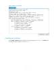
Figure 2 Statistics of an interface Creating an interface Select System > Interface from the navigation tree to enter the page shown in Figure 1. Click Add to enter the page for creating interfaces, as shown in Figure 3.
Figure 3 Create an interface Table 1 Configuration items of creating an interface Item Description Set the name for the interface or its subinterface. Interface Name Select an interface type in the drop-down list: • If you select a logical interface, set the interface number in the text box next to it. • If you select a physical interface, set the subinterface number in the text box next to it. Set the VLAN ID associated with the subinterface.
Item Description Set how the interface obtains an IP address: • None—Not to set an IP address for the interface. • Static Address—Manually assign an IP address for the interface. After selecting this option, you need to manually set the IP Address/Mask and Secondary IP Address/Mask items. IP Config • DHCP—The interface obtains an IP address through DHCP. • BOOTP—The interface obtains an IP address through BOOTP. • PPP Negotiate—The interface obtains an IP address through PPP negotiation.
Figure 4 Modify interface information The configuration items of editing an interface are similar to those of creating an interface. Table 2 Configuration items of editing an interface Item Description Interface Type Set the interface type, Electrical Port, Optical Port, or None. Display and set the interface status: • Connected—The interface is up and connected. You can click the Disable button to shut down the interface. • Not connected—The interface is up but not connected.
Managing interfaces at the CLI Configuring Ethernet interfaces The following types of Ethernet interfaces are available on your LB module: • Layer 2 Ethernet interfaces • Layer 3 Ethernet interfaces • Layer 2-Layer 3 Ethernet interfaces • Layer 2 Ethernet subinterfaces • Layer 3 Ethernet subinterfaces For more information about these Ethernet interfaces, see “Interface overview.
To do… Use the command… Remarks Enter system view system-view — Enter Ethernet interface view interface interface-type interface-number — Change the description of the interface description text Optional By default, the description of an interface is interface name Interface. For example, Ethernet1/1 Interface.
NOTE: • You can configure IP-related settings on an Ethernet subinterface. For more information, see the chapter “IP addressing configuration.” • For the local and remote Ethernet subinterfaces to transmit traffic correctly, configure them with the same subinterface number and VLAN ID. 3. Configuring loopback testing on an Ethernet interface If an Ethernet interface does not work normally, you can enable loopback testing on it to identify the problem.
CAUTION: After you change the operating mode of an Ethernet interface, all the settings of the Ethernet interface are restored to their defaults under the new operating mode. 5. Enabling subinterface rate statistics collection on an Ethernet interface After you enable subinterface rate statistics collection on an Ethernet interface, the LB module periodically refreshes the rate statistics on the subinterfaces of this Ethernet interface.
To do… Use the command… Optional Set the broadcast suppression threshold ratio broadcast-suppression ratio Set the multicast suppression threshold ratio multicast-suppression ratio Set the unknown unicast suppression threshold ratio 2. Remarks By default, Ethernet interfaces do not suppress broadcast traffic. Optional By default, Ethernet interfaces do not suppress multicast traffic. Optional unicast-suppression ratio By default, Ethernet interfaces do not suppress unknown unicast traffic.
To do… Use the command… Remarks Optional Set the MDI mode of the Ethernet interface mdi { across | auto | normal } By default, a copper Ethernet interface operates in auto mode to negotiate pin roles with its peer.
To do… Use the command… Configure the suppression time of link-layer-state changes on the Ethernet Interface timer hold seconds Remarks Optional 10 seconds by default NOTE: You can increase the polling interval to reduce network instability due to time delay or heavy congestion.
To do… Use the command… Remarks Enter system view system-view — Create a loopback interface and enter loopback interface view interface loopback interface-number — Set a description for the loopback interface description text Shut down the loopback interface shutdown Optional By default, the description of a loopback interface is interface name Interface. Optional By default, a loopback interface is up.
To do… Use the command… Remarks Clear the statistics on a loopback interface or the null interface reset counters interface [ interface-type [ interface-number | interface-number.
IP addressing configuration NOTE: You can configure IP addresses in the web interface or at the CLI. For more information about the web configuration procedure, see the chapter “Interface management configuration.” This chapter introduces how to configure IP addresses at the CLI only. IP addressing overview IP address classes IP addressing uses a 32-bit address to identify each host on a network.
Class Address range Remarks C 192.0.0.0 to 223.255.255.255 –– D 224.0.0.0 to 239.255.255.255 Multicast addresses. E 240.0.0.0 to 255.255.255.255 Reserved for future use except for the broadcast address 255.255.255.255. Special IP addresses The following IP addresses are for special use, and they cannot be used as host IP addresses: • IP address with an all-zero net ID: Identifies a host on the local network. For example, IP address 0.0.0.
Configuring IP addresses Assigning an IP address for an interface You may assign an interface multiple IP addresses, one primary and multiple secondaries. Generally, you only need to assign the primary address to an interface. In some cases, you need to assign secondary IP addresses to the interface. For example, if the interface connects to two subnets, to enable the LB module to communicate with all hosts on the LAN, you need to assign a primary IP address and a secondary IP address to the interface.
Figure 7 Network diagram for IP address configuration Configuration procedure # Assign a primary IP address and a secondary IP address for Ten-GigabitEthernet 0/0.1. system-view [LB] interface Ten-GigabitEthernet 0/0.1 [LB-Ten-GigabitEthernet0/0.1] ip address 172.16.1.1 255.255.255.0 [LB-Ten-GigabitEthernet0/0.1] ip address 172.16.2.1 255.255.255.0 sub # Set the gateway address to 172.16.1.1 on the PCs attached to subnet 172.16.1.0/24, and to 172.16.2.1 on the PCs attached to subnet 172.16.2.0/24.
Reply from 172.16.2.2: bytes=56 Sequence=4 ttl=255 time=26 ms Reply from 172.16.2.2: bytes=56 Sequence=5 ttl=255 time=26 ms --- 172.16.2.2 ping statistics --5 packet(s) transmitted 5 packet(s) received 0.00% packet loss round-trip min/avg/max = 25/25/26 ms The output information shows that LB can communicate with the hosts on subnet 172.16.2.0/24. # Ping a host on subnet 172.16.1.0/24 from a host on subnet 172.16.2.0/24 to check the connectivity. Host B can be successfully pinged from Host A.
MAC address table configuration NOTE: • The MAC address table can contain only Layer 2 Ethernet ports. • This document covers only the configuration of static, dynamic, and blackhole MAC address table entries. The configuration of multicast MAC address entries is not introduced here. Overview An Ethernet device uses a MAC address table for forwarding frames through unicast instead of broadcast. This table describes from which port a MAC address (or host) can be reached.
You can manually add MAC address entries to the MAC address table of the device to bind specific user devices to the port. Because manually configured entries have higher priority than dynamically learned ones, this prevents hackers from stealing data using forged MAC addresses. Types of MAC address table entries A MAC address table may contain the following types of entries: • Static entries, which are manually added and never age out.
Configuring a MAC address table in the web Adding a MAC address entry Select Network > MAC > MAC from the navigation tree to enter the MAC address entry list page, as shown in Figure 9. Figure 9 MAC address entry list page Click Add to enter the MAC address entry adding page, as shown in Figure 10. Figure 10 Add a MAC address entry Table 4 Configuration items for adding a MAC address entry Item Description MAC Type the MAC address you want to add.
Item Description VLAN ID of the VLAN to which the MAC address belongs. Port Port to which the MAC address belongs. This configuration item is not required for blackhole MAC address entries. Setting the aging time for MAC address entries Select Network > MAC > Confoguration from the navigation tree to enter the page for setting the MAC address entry aging time, as shown in Figure 11.
• Select Network > MAC > MAC from the navigation tree to enter the MAC address entry list page, click Add, and make the following configurations on the page as shown in Figure 12. Figure 12 Create a static MAC address entry • Enter MAC address 000f-e235-dc71. • Select static in the Type drop-down list. • Select 1 in the VLAN drop-down list. • Select Ten-GigabitEthernet0/0 in the Port drop-down list. • Click Apply. # Create a blackhole MAC address entry.
Figure 14 Set the aging time for MAC address entries • Select the Aging Time option and enter 500 as the aging time. • Click Apply. Configuring the MAC address table at the CLI The configuration tasks discussed in the following sections are all optional and can be performed in any order. Configuring MAC address table entries To fence off MAC address spoofing attacks and improve port security, you can manually add MAC address table entries to bind ports with MAC addresses.
Configuring the aging timer for dynamic MAC address entries The MAC address table on your LB module uses an aging timer for dynamic MAC address entries for security and efficient use of table space. If a dynamic MAC address entry has failed to update before the aging timer expires, the LB module deletes the entry. This aging mechanism ensures that the MAC address table could promptly updated to accommodate the latest network changes. Set the aging timer appropriately.
# Add a destination blackhole MAC address entry. [Sysname] mac-address blackhole 000f-e235-abcd vlan 1 # Set the aging timer for dynamic MAC address entries to 500 seconds. [Sysname] mac-address timer aging 500 # Display the MAC address entry for port Ten-GigabitEthernet 0/0.
Layer 2 forwarding configuration NOTE: The LB module supports Layer 2 forwarding configuration only in the command line interfaces (CLIs). Layer 2 forwarding overview Layer 2 forwarding involves general, inline, and inter-VLAN Layer 2 forwarding. General Layer 2 forwarding If the destination MAC address of an incoming packet matches the MAC address of the receiving Layer 3 interface, the device forwards the packet through that interface.
The LB module replaces the VLAN tag of the packet with its own VLAN tag and then handles the packet according to security settings. The LB module replaces its VLAN tag of the packet with that contained in the interface number of the egress subinterface and sends it to the switch (the egress subinterface is found through a MAC address table lookup). The switch forwards the packet toward the destination.
To do… Use the command… Remarks Required Assign an interface to the inline Layer 2 forwarding entry By default, the interface does not belong to any inline Layer 2 forwarding entry. port inline-interfaces id Two interfaces must be assigned to the forward-type inline forwarding entry while one interface is required for the reflect or blackhole type.
Create two subinterfaces for the Ten-GigabitEthernet interface, and use the IDs of those two VLANs created on the switch as their interface numbers respectively. Set the link type of the subinterfaces as access and assign the two subinterfaces to VLAN X. • NOTE: To achieve Layer 2 forwarding between VLANs, you can create these VLANs on the switch and configure the same number of subinterfaces for the Ten-GigabitEthernet interface on the LB module. 1.
To do… Use the command… Remarks Configure the link type of the Ten-GigabitEthernet interface as trunk port link-type trunk Required Required Assign the trunk port to the specified VLANs port trunk permit vlan { vlan-id-list | all } Create a subinterface of the Ten-GigabitEthernet interface and enter subinterface view interface Ten-GigabitEthernet interface-number.
To do… Use the command… Remarks Display VLAN information display vlan [ vlan-id1 [ to vlan-id2 ] | all | dynamic | interface interface-type interface-number.subnumber | reserved | static ] Available in any view Forward-type inline Layer 2 forwarding configuration example Network requirements Configure forward-type inline Layer 2 forwarding between Ten-GigabitEthernet 0/0.1 and Ten-GigabitEthernet 0/0.2. Then packets received on Ten-GigabitEthernet 0/0.
Inter-VLAN Layer 2 forwarding configuration example Network requirements As shown in Figure 16, traffic between GigabitEthernet 3/0/1 and GigabitEthernet 3/0/2 is filtered by a LB module, and inter-VLAN Layer 2 forwarding needs to be configured. • Ten-GigabitEthernet 2/0/1 of the switch connects to Ten-GigabitEthernet 0/0 of the LB module. Configure the link type of the two interfaces as trunk. • Configure the operating mode of Ten-GigabitEthernet 2/0/1 as Layer 2.
[Sysname] interface Ten-GigabitEthernet 2/0/1 [Sysname-Ten-GigabitEthernet2/0/1] port link-type trunk [Sysname-Ten-GigabitEthernet2/0/1] port trunk permit vlan 102 103 [Sysname-Ten-GigabitEthernet2/0/1] port trunk pvid vlan 1000 Configure the LB module # Create VLAN 1000. system-view [Sysname] vlan 1000 [Sysname-vlan1000] quit # Configure the link type of Ten-GigabitEthernet 0/0 as trunk and operating mode as Layer 2. Assign the trunk port to VLAN 102, VLAN 103, and VLAN 1000.
VLAN configuration Introduction to VLAN VLAN overview Ethernet is a network technology based on the Carrier Sense Multiple Access/Collision Detect (CSMA/CD) mechanism. As the medium is shared, collisions and excessive broadcasts are common on Ethernet networks. To address the issue, virtual LAN (VLAN) was introduced to break a LAN down into separate VLANs. VLANs are isolated from each other at Layer 2. A VLAN is a bridging domain, and all broadcast traffic is contained within it, as shown in Figure 17.
The format of VLAN-tagged frames is defined in IEEE 802.1Q issued by Institute of Electrical and Electronics Engineers (IEEE) in 1999. In the header of a traditional Ethernet data frame, the field after the destination MAC address and the source MAC address is the Type field indicating the upper layer protocol type, as shown in Figure 18. Figure 18 Traditional Ethernet frame format IEEE 802.1Q inserts a four-byte VLAN tag after the DA&SA field, as shown in Figure 19.
Port-based VLAN Port-based VLANs group VLAN members by port. A port forwards traffic for a VLAN only after it is assigned to the VLAN. Port link type You can configure the link type of a port as access, trunk, or hybrid. The link types use the following VLAN tag handling methods: • An access port belongs to only one VLAN. Usually, ports directly connected to PCs are configured as access ports. • A trunk port can carry multiple VLANs to receive and send traffic for them.
Port type Actions (in the inbound direction) Untagged frame Tagged frame Actions (in the outbound direction) • Removes the tag and sends Trunk Checks whether the PVID is permitted on the port: • If yes, tags the frame with the PVID tag. the frame if the frame carries the PVID tag and the port belongs to the PVID. • Receives the frame if its VLAN is carried on the port. • Drops the frame if its VLAN is not carried on the port.
Figure 20 VLAN configuration page NOTE: As shown in Figure 20, when you type a VLAN range in the VLAN Range box and then click Select, the table below lists information about all VLANs within this range, which makes the operation much easier when the LB module contains a large number of VLANs. To remove all VLANs within this range, click Remove. Click Add to enter the page for creating a VLAN, as shown in Figure 21.
Figure 22 Modify a VLAN Table 8 Configuration items of modifying a VLAN Item Description ID Displays the ID of the VLAN to be modified. Description Untagged Member Tagged Member Set the description string of the VLAN. By default, the description string of a VLAN is its VLAN ID, such as VLAN 0001. Set the member type of the port to be modified in the VLAN.
Figure 24 Modify a port Table 9 Configuration items of modifying a port Item Description Port Displays the port to be modified. Untagged Member VLAN Displays the VLAN(s) to which the port belongs as an untagged member. Tagged Member VLAN Displays the VLAN(s) to which the port belongs as a tagged member. Untagged Set the target member type of the port.
Configuration procedure 1. Configure LB A NOTE: Before making the following configurations, check whether Ten-GigabitEthernet 0/0 operates in route mode. If yes, change its operating mode to bridge mode (to do that, select System > Interface from the navigation tree, and then find and select Ten-GigabitEthernet 0/0 to configure it accordingly); in addition, specify the security zone to which Ten-GigabitEthernet 0/0 belongs when the port is assigned to VLAN 2, VLANs 6 to 50, and VLAN 100.
• Click Ten-GigabitEthernet0/0 on the page that appears to enter the page displaying the port statistics of Ten-GigabitEthernet 0/0. Configuring a VLAN at the CLI Configuring VLAN Configuring basic VLAN settings Follow these steps to configure basic VLAN settings: To do… Use the command… Remarks Enter system view system-view — Create VLANs vlan { vlan-id1 [ to vlan-id2 ] | all } Optional Use this command to create VLANs in bulk.
You can assign the VLAN interface an IP address and specify it as the gateway of the VLAN to forward traffic destined for an IP network segment different from that of the VLAN.
To do… Use the command… Remarks Enter Ethernet interface view interface interface-type interface-number — Configure the link type of the port as access port link-type access Assign the access port to a VLAN port access vlan vlan-id Optional By default, all ports are access ports. Optional By default, all access ports belong to VLAN 1. NOTE: • Before assigning an access port to a VLAN, create the VLAN first. • The link type of Layer 2 Ethernet subinterfaces is fixed at access.
Follow these steps to assign a hybrid port to one or multiple VLANs: To do… Use the command… Remarks Enter system view system-view — Enter Ethernet interface view interface interface-type interface-number — Configure the link type of the port as hybrid port link-type hybrid Required By default, all ports are access ports.
Figure 26 Network diagram for port-based VLAN configuration 2. Configuration procedure • Configure LB A # Create VLAN 2, VLAN 6 through VLAN 50, and VLAN 100. system-view [LB A] vlan 2 [LB A-vlan2] quit [LB A] vlan 100 [LB A-vlan100] vlan 6 to 50 Please wait... Done. # Enter Ten-GigabitEthernet 0/0 interface view. [LB A] interface Ten-GigabitEthernet 0/0 # Configure Ten-GigabitEthernet 0/0 as a trunk port and configure its PVID as 100.
Allow jumbo frame to pass PVID: 100 Mdi type: auto Link delay is 0(sec) Port link-type: trunk VLAN passing : 2, 6-50, 100 VLAN permitted: 2, 6-50, 100 Trunk port encapsulation: IEEE 802.
As shown in Figure 27, the isolate-user-VLAN function is enabled on Switch B. VLAN 10 is the isolate-user-VLAN, and VLAN 2, VLAN 5, and VLAN 8 are secondary VLANs associated with VLAN 10 and are invisible to Switch A. Figure 27 An isolate-user-VLAN example Configuring an isolate-user-VLAN Configure the isolate-user-VLAN through the following tasks: 1. Configure the isolate-user-VLAN. 2. Configure the secondary VLANs. 3.
To do... Use the command Remarks • For access ports: Assign ports to each secondary VLAN and ensure that at least one port in a secondary VLAN takes the secondary VLAN as its PVID For the configuration procedure, see Assigning an access port to a VLAN.” Required • For hybrid ports: Use either approach.
Figure 28 Network diagram for isolate-user-VLAN configuration 2. Configuration procedure The following part provides only the configuration on LB A and LB B. • Configure LB A # Configure the isolate-user-VLAN. system-view [LB A] vlan 5 [LB A-vlan5] isolate-user-vlan enable [LB A-vlan5] port Ten-GigabitEthernet 0/0.5 [LB A-vlan5] quit # Configure the secondary VLANs. [LB A] vlan 3 [LB A-vlan3] port Ten-GigabitEthernet 0/0.
# Associate the isolate-user-VLAN with the secondary VLANs. [LB B-vlan4] quit [LB B] isolate-user-vlan 6 secondary 3 to 4 • Verification # Display the isolate-user-VLAN configuration on LB A. [LB A] display isolate-user-vlan Isolate-user-VLAN VLAN ID : 5 Secondary VLAN ID : 2-3 VLAN ID: 5 VLAN Type: static Isolate-user-VLAN type : isolate-user-VLAN Route Interface: not configured Description: VLAN 0005 Name: VLAN 0005 Broadcast MAX-ratio: 100% Tagged Ports: none Untagged Ports: XGE0/0.1 XGE0/0.
ARP configuration NOTE: The LB module supports ARP configuration only in the command line interfaces (CLIs). ARP overview ARP function The Address Resolution Protocol (ARP) is used to resolve an IP address into a physical address (Ethernet MAC address, for example). In an Ethernet LAN, when a LB module sends data to another device, it uses ARP to translate the IP address of that device to the corresponding MAC address. ARP message format ARP messages are classified into ARP requests and ARP replies.
• Sender protocol address: This field specifies the protocol address of the device sending the message. • Target hardware address: This field specifies the hardware address of the device the message is being sent to. • Target protocol address: This field specifies the protocol address of the device the message is being sent to. ARP operation Suppose that Host A and Host B are on the same subnet and Host A sends a packet to Host B, as shown in Figure 30. The resolution process is as follows: 1.
ARP table After obtaining the MAC address of a host, the LB card puts the IP-to-MAC mapping into its own ARP table. This mapping is used for forwarding packets with the same destination in future. An ARP table contains ARP entries, which fall into one of two categories: dynamic or static. Dynamic ARP entry A dynamic entry is automatically created and maintained by ARP. It can get aged, be updated by a new ARP packet, or be overwritten by a static ARP entry.
To do… Use the command… Remarks Configure a long static ARP entry arp static ip-address mac-address vlan-id interface-type interface-number Required Configure a short static ARP entry arp static ip-address mac-address Not configured by default. Required Not configured by default. CAUTION: • The vlan-id argument must be the ID of an existing VLAN where the ARP entry resides. The specified Ethernet interface must belong to that VLAN. The VLAN interface of the VLAN must be created.
After ARP entry check is disabled, the LB card can learn the ARP entry with a multicast MAC address, and you can also configure such a static ARP entry on the card. Follow these steps to enable ARP entry check: To do… Use the command… Remarks Enter system view system-view — Enable ARP entry check arp check enable Optional Disabled by default.
ARP configuration example Network requirements As shown in Figure 31, hosts are connected to LB module, which is connected to Router through interface Ten-GigabitEthernet 0/0.1 belonging to VLAN 10. The IP address of Router is 192.168.1.1/24. The MAC address of Router is 00e0-fc01-0000. To enhance communication security for Router and, LB module, static ARP entries are configured on LB module.
IP Address MAC Address VLAN ID Interface Aging Type 192.168.1.1 00e0-fc01-0000 10 XGEth0/0.
Gratuitous ARP configuration NOTE: The LB module supports gratuitous ARP configuration only in the CLIs. Introduction to gratuitous ARP In a gratuitous ARP packet, the sender IP address and the target IP address are the IP address of the sending device, the sender MAC address is the MAC address of the sending device, and the target MAC address is the broadcast address ff:ff:ff:ff:ff:ff. An LB card sends a gratuitous ARP packets to: • Determine whether its IP address is already used by another device.
3. Prevent the virtual IP address of a VRRP group from being used by a host The master router of a VRRP group can periodically send gratuitous ARP packets to the hosts on the local network, so that the hosts can update local ARP entries and avoid using the virtual IP address of the VRRP group. If the virtual IP address of the VRRP group is associated with a virtual MAC address, the sender MAC address in the gratuitous ARP packet takes the virtual MAC address of the virtual router.
NOTE: • You can enable periodic sending of gratuitous ARP packets on a maximum of 1024 interfaces. • Periodic sending of gratuitous ARP packets takes effect only when the link of the enabled interface goes up and an IP address has been assigned to the interface. • If you change the interval for sending gratuitous ARP packets, the configuration is effective at the next sending interval.
Proxy ARP configuration NOTE: The LB module supports proxy ARP configuration only in the CLIs.
A main advantage of proxy ARP is that it is added on a single router without disturbing routing tables of other routers in the network. Proxy ARP acts as the gateway for IP hosts that are not configured with a default gateway or do not have routing capability. Local proxy ARP As shown in Figure 33, Host A and Host B belong to VLAN 2, but are isolated at Layer 2. Host A connects to Ethernet 1/3 while Host B connects to Ethernet 1/1.
To do… Use the command… Remarks Enable local proxy ARP local-proxy-arp enable [ ip-range startIP to endIP ] Required Disabled by default.
system-view [LB] interface Ten-GigabitEthernet 0/0.2 [LB-Ten-GigabitEthernet0/0.2] ip address 192.168.10.99 255.255.255.0 # Enable proxy ARP on interface Ten-GigabitEthernet 0/0.2. [LB-Ten-GigabitEthernet0/0.2] proxy-arp enable [LB-Ten-GigabitEthernet0/0.2] quit # Specify the IP address of interface Ten-GigabitEthernet 0/0.1. [LB] interface Ten-GigabitEthernet 0/0.1 [LB-Ten-GigabitEthernet0/0.1] ip address 192.168.20.99 255.255.255.0 # Enable proxy ARP on interface Ten-GigabitEthernet 0/0.1.
Configuration procedure 1. Configure Switch # Add Ethernet 1/3, Ethernet 1/1 and Ethernet 1/2 to VLAN 2. Configure port isolation on Host A and Host B.
Figure 36 Network diagram for local proxy ARP configuration in isolate-user-VLAN LB XGE0/0.1 192.168.10.100/16 Isolate-user-vlan 5 Secondary VLAN 2 and 3 Eth1/2 VLAN 5 Eth1/3 VLAN 2 Host A Switch Eth1/1 VLAN 3 192.168.10.99/16 Host B 192.168.10.200/16 Configuration procedure 1. Configure Switch # Create VLAN 2, VLAN 3, and VLAN 5 on Switch. Add Ethernet 1/3 to VLAN 2, Ethernet 1/1 to VLAN 3, and Ethernet 1/2 to VLAN 5.
Layer 3 forwarding configuration NOTE: • Layer 3 subinterface forwarding configuration of a LB module is used in the configuration examples of all the other modules. • For the configurations on the switches involved in the configuration examples of the modules in other volumes, see the configuration on the switch in the Layer 3 subinterface forwarding configuration example. • The LB module supports Layer 3 forwarding configuration only in the command line interfaces (CLIs).
Inter-VLAN Layer 3 forwarding If the destination MAC address of an incoming packet matches the MAC address of a VLAN interface, the LB module removes the Layer 2 header and delivers the packet to the Layer 3 forwarding engine. The following prerequisites are necessary for inter-VLAN Layer 3 forwarding: • The ingress interface and egress interface on the switch belong to different VLANs.
NOTE: To achieve Layer 3 forwarding between VLANs, you can create these VLANs on the switch and configure the same number of subinterfaces for the ten-GigabitEthernet interface on the LB module.
To do… Use the command Assign an IP address to the subinterface ip address ip-address { mask | mask-length } [ sub ] Create another subinterface and enter subinterface view interface Ten-GigabitEthernet interface-number.subnumber Remarks Required By default, no IP address is configured for the subinterface.
• Create two VLAN interfaces with the same numbers as VLANs created on the switch for the ten-GigabitEthernet interface. • Assign IP addresses for the two VLAN interfaces. NOTE: To achieve Layer 3 forwarding between VLANs, you can create these VLANs on the switch and configure the same number of VLAN interfaces for the ten-GigabitEthernet interface on the LB module.
To do… Use the command… Remarks Configure the link type of the ten-GigabitEthernet interface as trunk port link-type trunk Required Assign the trunk port to the specified VLANs port trunk permit vlan { vlan-id-list | all } Create a VLAN interface and enter its view interface vlan-interface vlan-interface-id Assign an IP address to the VLAN interface ip address ip-address { mask | mask-length } [ sub ] Create another VLAN interface and enter its view interface vlan-interface vlan-interface-id A
• Configure the operating mode of GigabitEthernet 3/0/1 and GigabitEthernet 3/0/2 of the switch as access. Assign them to VLAN 102 and VLAN 103 respectively. • Ten-GigabitEthernet 2/0/1 of the switch connects to ten-GigabitEthernet 0/0 of the LB module. Configure ten-GigabitEthernet 2/0/1 as a trunk port. • Configure the operating mode of the LB module's ten-GigabitEthernet interface as Layer 3. Configure two subinterfaces, ten-GigabitEthernet 0/0.1 and ten-GigabitEthernet 0/0.
# Configure two subinterfaces for ten-GigabitEthernet 0/0. Set their encapsulation type to dot1q and associate them to with VLANs created on the switch. Assign IP addresses for the subinterfaces. [Sysname-Ten-GigabitEthernet0/0] interface Ten-GigabitEthernet0/0.1 [Sysname-Ten-GigabitEthernet0/0.1] vlan-type dot1q vid 102 [Sysname-Ten-GigabitEthernet0/0.1] ip address 102.0.0.3 24 [Sysname-Ten-GigabitEthernet0/0.1] interface Ten-GigabitEthernet0/0.2 [Sysname-Ten-GigabitEthernet0/0.
[Sysname-vlan102] vlan 103 [Sysname-vlan103] port GigabitEthernet 3/0/2 [Sysname-vlan103] quit # Configure the link type of ten-GigabitEthernet 2/0/1 as trunk. Assign the port to VLAN 102 and VLAN 103. [Sysname] interface Ten-GigabitEthernet 2/0/1 [Sysname-Ten-GigabitEthernet2/0/1] port link-type trunk [Sysname-Ten-GigabitEthernet2/0/1] port trunk permit vlan 102 103 2. Configure the LB module. # Create VLAN 102 and VLAN 103.
NAT configuration Overview Introduction to NAT Network Address Translation (NAT) provides a way of translating the IP address in an IP packet header to another IP address. In practice, NAT is primarily used to allow users using private IP addresses to access public networks. With NAT, a smaller number of public IP addresses are used to meet public network access requirements from a larger number of private hosts, and thus NAT effectively alleviating the depletion of IP addresses.
• Upon receipt of the packet, the NAT gateway checks the IP header. Finding that the packet is destined to the external network, the NAT gateway translates the private source IP address 192.168.1.3 to the globally unique IP address 20.1.1.1 and then forwards the packet to the external server. Meanwhile, the NAT gateway records the mapping between the two addresses in its NAT table. • After receiving a response from the external server, the NAT gateway uses the destination IP address 20.1.1.
NAT control can be achieved through ACLs. Only packets matching the ACL rules are served by NAT. NAPT Network Address Port Translation (NAPT) is a variation of NAT. It allows multiple internal addresses to be mapped to the same public IP address, which is called multiple-to-one NAT or address multiplexing. NAPT mapping is based on both the IP address and the port number. With NAPT, packets from multiple internal hosts are mapped to the same external IP address with different port numbers.
packet from the internal server arrives, the NAT device translates the private source address of the packet into the public IP address. DNS mapping As introduced, you can specify a public IP address and port number for an internal server on the public network interface of a NAT gateway, so that external users can access the internal server using its domain name or pubic IP address.
device if one device fails. However, if the devices select the same IP addresses from their address pool and assign them the same port numbers, reverse sessions on the two devices are the same. As a result, session data cannot be backed up between the devices. To solve the problem, the low-priority address pool attribute is introduced to NAT. You can configure address pools on the two devices to have different priorities. For example, suppose that two addresses pools, 100.0.0.1 through 100.0.0.
Table 11 Static NAT configuration task list Task Remarks Creating a static address mapping Enabling static NAT on an interface Required Static NAT supports two modes, one-to-one and net-to-net. Required Configure static NAT on an interface. Configuring an internal server Perform the tasks in Table 12 to configure an internal server.
Figure 43 Dynamic NAT configuration page Figure 44 Add NAT Address Pool page Table 13 NAT address pool configuration items Item Description Index Specify the index of an address pool. Start IP Address Specify the start IP address of the address pool. End IP Address Specify the end IP address of the address pool. The end IP address must be identical to or higher than the start IP address. Configure the address pool as a low-priority or a non low-priority address pool.
Configuring dynamic NAT Select Security > NAT > Dynamic NAT from the navigation tree to enter the page shown in Figure 43. In the Dynamic NAT field where all dynamic NAT policies are displayed, click Add to enter the Add Dynamic NAT page shown in Figure 45. Figure 45 Add Dynamic NAT page Table 14 Dynamic NAT configuration items Item Description Interface Specify an interface on which dynamic NAT is to be enabled. Specify an ACL for dynamic NAT.
Creating a static address mapping Select Security > NAT > Static NAT from the navigation tree to enter the page, as shown in Figure 46. In the Static Address Mapping field where static address mappings are displayed, click Add to enter the Add Static Address Mapping page shown in Figure 47. Figure 46 Static NAT configuration page Figure 47 Add Static Address Mapping page Table 15 Static NAT configuration item Item Description Specify a name of the VPN instance to which the internal IP addresses belong.
Enabling static NAT on an interface Select Security > NAT > Static NAT from the navigation tree to enter the page shown in Figure 46. In the Interface Static Translation field where static NAT entries configured for interfaces are displayed, click Add to enter the Enable Interface Static Translation page shown in Figure 48.
Figure 49 Internal server configuration page Figure 50 Add Internal Server page Table 17 Internal server configuration items Item Description Interface Specify an interface to which the internal server policy is applied. Protocol Type Select or specify the type of the protocol to be carried by IP. External IP Address Specify the public IP address for the internal server. You can type an IP address, or use the IP address of an interface.
Item Description Specify the global port number(s) for the internal server. This option is available when 6(TCP) or 17(UDP) is selected as the protocol type. You can: • Use the single box to specify a global port. Global Port • Use the double boxes to specify a range of global ports each of which has a one-to-one correspondence with the specified internal IP address. The number you typed in the right box should be higher than that in the left box.
Figure 51 Add DNS-MAP page Table 18 DNS mapping configuration items Item Description Protocol Select the protocol supported by an internal server. Global IP Specify the external IP address of the internal server. Global Port Specify the port number of the internal server. Domain Specify the domain name of the internal server. Return to Internal server configuration task list. NAT configuration examples NAT configuration example 1.
Figure 53 Define ACL 2001 • Type 2001 in ACL Number. • Select Config in Match Order. • Click Apply. • Click the icon in the Operation column corresponding to ACL 2001 to enter the ACL 2001 configuration page, click Add, and then perform the following operations, as shown in Figure 54. Figure 54 Configure ACL 2001 to permit users on network 10.110.10.0/24 to access the Internet • Select Permit in Operation. • Select the Source IP Address checkbox and then type 10.110.10.0. • Type 0.0.0.
# Configure a NAT address pool. • Select Security > NAT > Dynamic NAT from the navigation tree, click Add, and then perform the following operations, as shown in Figure 56. Figure 56 Configure NAT address pool 0 • Type 0 in Index. • Type 202.38.1.2 in Start IP Address. • Type 202.38.1.3 in End IP Address. • Click Apply. # Configure dynamic NAT. • Click Add in the Dynamic NAT field and perform the following operations, as shown in Figure 57.
10.110.10.3/16, for the Web server 1 is 10.110.10.1/16, and for the Web server 2 is 10.110.10.2/16. The company has three public IP addresses from 202.38.1.1/24 through 202.38.1.3/24. Specifically, the company has the following requirements: • External hosts can access internal servers using public address 202.38.1.1/24. • Port 8080 is used for Web server 2. Figure 58 Internal server network diagram 10.110.10.1/16 10.110.10.2/16 Web server 1 Web server 2 XGE0/0.1 10.110.10.10/16 XGE0/0.2 202.38.1.
• Select 6(TCP) for Protocol Type. • Click the radio button next to Assign IP Address, and then type 202.38.1.1 in Global IP. • Select the upper radio button next to Global Port and type 21. • Type 10.110.10.3 in Internal IP. • Type 21 in Internal Port. • Click Apply. # Configure the Web server 1. • Click Add in the Internal Server field and perform the following operations, as shown in Figure 60. Figure 60 Configure internal Web server 1 • Select Ten-GigabitEthernet0/0.2 for Interface.
Figure 61 Configure internal Web server 2 • Select Ten-GigabitEthernet0/0.2 for Interface. • Select 6(TCP) for Protocol Type. • Click the radio button next to Assign IP Address, and then type 202.38.1.1 for Global IP. • Select the upper radio button next to Global Port and type 8080. • Type 10.110.10.2 in Internal IP. • Type 80 in Internal Port. • Click Apply.
NOTE: If the NAT configuration (address translation or internal server configuration) on an interface is changed, HP recommends that you save the configuration and reboot the LB module, to avoid problems. The following are the possible problems: After you delete the NAT-related configuration, address translation can still work for sessions already created; if you configure NAT when NAT is running, the same configuration may have different results because of different configuration orders.
To do… Use the command… Remarks Enter system view system-view — Configure a one-to-one static NAT mapping nat static local-ip global-ip Required Enter interface view interface interface-type interface-number — Enable static NAT on the interface nat outbound static [ track vrrp virtual-router-id ] Required 2. Configuring net-to-net static NAT Net-to-net static NAT translates a private network into a public network.
NOTE: If both the inbound and outbound interfaces of a NAT device are associated with an address pool, a packet matching both of them uses an address from the address pool associated with the outbound interface for address translation. 1. Configuration prerequisites • Configure an ACL • Configure an address pool NOTE: • For more information about ACL, see Security Configuration Guide. • For how to configure an address pool, see “Configuring NAT address pool.” 2.
To do… Use the command… Remarks Configure NAPT by associating an ACL with an IP address pool on the outbound interface for translating both IP address and port number nat outbound [ acl-number ] [ address-group group-number [ track vrrp virtual-router-id ] Required Configuring an internal server Introduction to internal server To configure an internal server, you need to map an external IP address and port number to the internal server.
Configuring DNS mapping With DNS mapping, an internal host can access an internal server on the same private network by using the domain name of the internal server when the DNS server resides on the public network.
Figure 62 NAT network diagram 2. Configuration procedure # Configure address pool 1. system-view [LB] nat address-group 1 202.38.1.2 202.38.1.3 # Configure ACL 2001, permitting only users from network segment 10.110.10.0/24 to access the Internet. [LB] acl number 2001 [LB-acl-basic-2001] rule permit source 10.110.10.0 0.0.0.255 [LB-acl-basic-2001] rule deny [LB-acl-basic-2001] quit # Associate address pool 1 and ACL 2001 with the outbound interface Ten-GigabitEthernet0/0.2.
Figure 63 Network diagram for common internal server configuration 10.110.10.1/16 10.110.10.2/16 Web server 1 Web server 2 XGE0/0.1 10.110.10.10/16 XGE0/0.2 202.38.1.1/24 LB FTP server SMTP server 10.110.10.3/16 10.110.10.4/16 2. Internet Host Configuration procedure # Enter interface Ten-GigabitEthernet 0/0.2 view. system-view [LB] interface Ten-GigabitEthernet 0/0.2 # Configure the internal FTP server. [LB-Ten-GigabitEthernet0/0.2] nat server protocol tcp global 202.38.1.
Figure 64 Network diagram for NAT DNS mapping 10.110.10.1/16 10.110.10.2/16 202.38.1.4/24 Web server FTP server DNS server XGE0/0.1 10.110.10.10/16 XGE0/0.2 202.38.1.1/24 Internet LB 2. Host A Host B 10.110.10.3/16 202.38.1.10/24 Configuration procedure system-view [LB] interface Ten-Gigabitethernet 0/0.2 # Configure the internal web server. [LB-Ten-Gigabitethernet0/0.2] 10.110.10.1 www nat server protocol tcp global 202.38.1.2 inside nat server protocol tcp global 202.38.
Troubleshooting NAT Symptom 1: abnormal translation of IP addresses Solution: Enable debugging for NAT. Try to locate the problem based on the debugging display. Use other commands, if necessary, to further identify the problem. Pay special attention to the source address after the address translation and ensure that this address is the address that you intend to change to. If not, there may be an address pool bug.
ALG configuration NOTE: The LB module supports configuring ALG only in the command line interface. ALG overview The Application Level Gateway (ALG) feature is used to process application layer packets. Usually, Network Address Translation (NAT) translates only IP address and port information in packet headers; it does not analyze fields in application layer payloads. However, the packet payloads of some protocols may contain IP address or port information, which, if not translated, may cause problems.
• SQLNET (a language in Oracle) • Trivial File Transfer Protocol (TFTP) The following describes the operation of an ALG-enabled HP load balancing (LB) module, taking FTP as an example. As shown in Figure 65, the host in the outside network accesses the FTP server in the inside network in passive mode through the LB module. Figure 65 Network diagram for ALG-enabled FTP application in passive mode The communication process includes the following stages: 1.
4. Exchanging data The host and the FTP server exchange data through the established data connection. Enabling ALG Follow these steps to enable ALG: To do... Use the command...
[LB] alg ftp # Configure NAT. [LB] interface Ten-GigabitEthernet 0/0.1 [LB-Ten-GigabitEthernet0/0.1] nat outbound 2001 address-group 1 # Configure internal FTP server. [LB-Ten-GigabitEthernet0/0.1] 192.168.1.2 ftp nat server protocol tcp global 5.5.5.10 ftp inside SIP/H.323 ALG configuration example NOTE: H.323 ALG configuration is similar to SIP ALG configuration. The following takes SIP ALG configuration as an example.
NBT ALG configuration example Network requirements As shown in Figure 68, a company accesses the Internet through a LB module with NAT and ALG enabled. The company provides NBT services to the outside. The inside network segment of the company is 192.168.1.0/24. Configure NAT and ALG on the LB module to meet the following requirements: • Host B can access the WINS server and Host A with host names. • Host A uses 5.5.5.9 as its external IP address, and the WINS server uses 5.5.5.
Static route configuration Static routes are manually configured. If a network’s topology is simple, you only need to configure static routes to implement network communication. The proper configuration and usage of static routes can improve network performance and ensure bandwidth for important network applications. The disadvantage of using static routes is that they cannot adapt to network topology changes. If a fault or a topological change occurs in the network, the routes will be unreachable.
Item Priority Remarks Type the static route preference The static route preference defaults to 60. Static route configuration example Network requirements Configure IP addresses and masks for the interfaces and hosts as shown in Figure 71. Configure static routes between the hosts so that any two hosts can communicate with each other. Figure 71 Network diagram for static route configuration Configuration considerations 1. On Device A, configure a static route to Device B. 2.
Figure 72 Configure a static route on Device A • Type 0.0.0.0 as the destination IP address. • Select 0.0.0.0 from the mask drop-down list. • Type 1.1.4.2 as the nexthop. • Click Apply. # Configure static routes on Device B. • Select Network > Static Routing from the navigation tree of Device B and click Add. • Type 1.1.2.0 as the destination IP address. • Select 255.255.255.0 from the mask drop-down list. • Type 1.1.4.1 as the nexthop. • Click Apply. • Click Add. • Type 1.1.3.
Reply from 1.1.2.2: bytes=32 time=1ms TTL=128 Reply from 1.1.2.2: bytes=32 time=1ms TTL=128 Reply from 1.1.2.2: bytes=32 time=1ms TTL=128 Reply from 1.1.2.2: bytes=32 time=1ms TTL=128 Ping statistics for 1.1.2.2: Packets: Sent = 4, Received = 4, Lost = 0 (0% loss), Approximate round trip times in milli-seconds: Minimum = 1ms, Maximum = 1ms, Average = 1ms # Traceroute Host A on Host B (suppose the host runs Windows XP). C:\Documents and Settings\Administrator>tracert 1.1.2.2 Tracing route to 1.1.2.
NOTE: • When configuring a static route, the static route does not take effect if you specify the next hop address first and then configure it as the IP address of a local interface, such as Ethernet interface and VLAN interface. • If you do not specify the preference when configuring a static route, the default preference will be used. Reconfiguring the default preference applies only to newly created static routes.
# Configure two static routes on Device B. system-view [DeviceB] ip route-static 1.1.2.0 255.255.255.0 1.1.4.1 [DeviceB] ip route-static 1.1.3.0 255.255.255.0 1.1.5.6 # Configure a default route on Device C. system-view [DeviceC] ip route-static 0.0.0.0 0.0.0.0 1.1.5.5 3. Configure the hosts. The default gateways for Host A, Host B and Host C are 1.1.2.3, 1.1.6.1, and 1.1.3.1 respectively. The configuration procedure is omitted. 4. Display the configuration result.
Pinging 1.1.2.2 with 32 bytes of data: Reply from 1.1.2.2: bytes=32 time=1ms TTL=128 Reply from 1.1.2.2: bytes=32 time=1ms TTL=128 Reply from 1.1.2.2: bytes=32 time=1ms TTL=128 Reply from 1.1.2.2: bytes=32 time=1ms TTL=128 Ping statistics for 1.1.2.2: Packets: Sent = 4, Received = 4, Lost = 0 (0% loss), Approximate round trip times in milli-seconds: Minimum = 1ms, Maximum = 1ms, Average = 1ms # Use the tracert command on Host B to check reachability to Host A.
RIP configuration NOTE: The LB module supports configuring RIP only in the web interface. RIP is a simple Interior Gateway Protocol (IGP), mainly used in small-sized networks, such as academic networks and simple LANs. It is not applicable to complex networks. RIP is widely used in practical networking because it is easy to implement, configure, and maintain.
Table 21 RIP global configuration items Item Description Enable RIP (enable all interfaces automatically) Enable RIP on all interfaces. Import static routes Configure RIP to redistribute static routes. Return to RIP configuration task list. Configuring interface RIP Select Network > RIP from the navigation tree to enter the RIP configuration page. If RIP is enabled, the More button is displayed. Click More to display the hidden RIP interface list, as shown in Figure 75.
Item Description Set whether to allow the receiving/sending of RIP packets on the interface. Work State • On: Allows the receiving/sending of RIP packets on the interface. • Off: Disallows the receiving/sending of RIP packets on the interface. Specify a RIP version for the interface. • Default: Indicates the interface can send RIPv1 broadcasts and can receive RIPv1 broadcast and unicast packets, and RIPv2 broadcast, multicast, and unicast packets.
2. Enable RIP. # Configure LB A. • Select Network > RIP from the navigation tree of LB A. • Select the Enable RIP(Enable all interfaces automatically) check box, as shown in Figure 78. • Click Apply. Figure 78 Enable RIP # Configure LB B. • Select Network > RIP from the navigation tree of LB B. • Select the Enable RIP(Enable all interfaces automatically) check box, as shown in Figure 78. • Click Apply. Configuration verification # Display active routes of LB A.
Figure 80 RIP configuration result II Configuration guidelines 1. RIP multi-process is not supported on the web interface. Enabling RIP creates process 1, and disabling RIP removes process 1. 2. After you enable RIP, it is enabled on all the interfaces automatically. Enabling RIP on a specific interface is not supported on the web interface; instead, you can set the Work State of a RIP interface to enable/disable the receiving/sending of RIP packets. 3.
OSPF configuration NOTE: The LB module supports configuring OSPF only in the web interface. Open Shortest Path First (OSPF) is a link state interior gateway protocol developed by the OSPF working group of the Internet Engineering Task Force (IETF). Now, OSPF version 2 (RFC 2328) is used. Configuration prerequisites Configure the link layer protocol and IP addresses for interfaces so that neighboring nodes can communicate with each other. Configuration overview Make a proper plan before configuring OSPF.
Task Remarks Optional Configure timers and OSPF authentication parameters on the OSPF interface. IMPORTANT: Configuring OSPF interfaces To prevent leakage of routing information and guard against attacks to OSPF routers, OSPF provides the packet authentication function. To establish neighboring relationship with a router, an OSPF router sends packets containing the preconfigured password for authentication.
Figure 82 Tabs on the OSPF area configuration page 126
Figure 83 OSPF area configuration page Table 25 OSPF area configuration items Item Description Area ID Type an area ID. Select an area type, including Normal, Stub, and NSSA. Area Type IMPORTANT: The type of a backbone area (with area ID 0) can only be configured as Normal. Enable all interfaces Network Address Network Items Network Mask Set whether to enable OSPF on all the interfaces.
Configuring OSPF interfaces Select Network > OSPF from the navigation tree to enter the OSPF configuration page. After you complete OSPF area configurations, click the More button to display the hidden OSPF interface list, as shown in Figure 84. Then, click the icon to enter the configuration page of the specified OSPF interface, as shown in Figure 85.
Item Description Set the OSPF dead interval. Within the dead interval, if the interface receives no hello packet from the neighbor, it declares that the neighbor is down. Dead Interval The default dead interval is 40 seconds on P2P, Broadcast interfaces and 120 seconds on P2MP and NBMA interfaces. The dead interval should be at least four times the hello interval on an interface. The interfaces on a specific network segment must have the same dead interval.
Item Description Current state of the interface, which can be: • Down, indicating no packet is sent or received through the interface. • Loopback • Waiting, indicating the interface starts to send and receive Hello packets and attempts to State find the DR and BDR on the network. • P-2-P, indicating the interface will send Hello packets at the hello interval, and attempts to establish adjacency with the peer router. • DR, indicating the router is a designated router (DR) of the network.
Item Description Current state of the neighbor, which can be: • Down, indicating the initial state of the neighboring relationship. • Init, indicating a Hello packet is received from the neighbor before the neighbor is down, but it does not contain the router ID. In such cases, bidirectional communication is not available. • Attempt, which is available the neighbor of an NBMA network only. It indicates the router receives no information from the neighbor, but it still attempts to contact the neighbor.
Figure 89 Enable OSPF • Click Apply. After you enable OSPF, the following figure is displayed. Figure 90 The web page displayed after OSPF is enabled • Click Add on the Area Configuration tab and make the following configurations on Figure 91. • Type 0 for Area ID. • Select Normal for Area Type. • Type 10.1.1.0 for Network Address, and select 0.0.0.255 for Network Mask. Then, click Add Network. • Click Apply.
Figure 91 Configure area 0 • Click Add on the Area Configuration tab and make the following configurations on Figure 92. • Type 1 for Area ID. • Select NSSA for Area Type. • Type 10.2.1.0 for Network Address, and select 0.0.0.255 for Network Mask. Then, click Add Network. • Click Apply.
Figure 92 Configure area 1 # Configure Device B. • Select Network > OSPF from the navigation tree of Device B. • Select the Enable OSPF check box. • Click Apply. • Click Add on the Area Configuration tab. • Type 0 for Area ID. • Select Normal for Area Type. • Type 10.1.1.0 for Network Address, and select 0.0.0.255 for Network Mask. Then, click Add Network. • Click Apply. • Click Add on the Area Configuration tab. • Type 2 for Area ID. • Select Normal for Area Type. • Type 10.3.1.
# Configure Device C. • Select Network > OSPF from the navigation tree of Device C. • Select the Enable OSPF check box. • Select the Import static routes check box. • Click Apply. • Click Add on the Area Configuration tab. • Type 1 for Area ID. • Select NSSA for Area Type. • Type 10.2.1.0 for Network Address, and select 0.0.0.255 for Network Mask. Then, click Add Network. • Type 10.4.1.0 for Network Address, and select 0.0.0.255 for Network Mask. Then, click Add Network. • Click Apply.
# Display the routing table of Device A. Select Network > Routing Info from the navigation tree of Device A. The OSPF routes 3.2.1.0/24, 10.3.1.0/24, 10.4.1.0/24 and 10.5.1.0/24 that are learned after OSPF is enabled are displayed in the routing table, as shown in Figure 94. Figure 94 OSPF configuration result II Configuration guidelines 1. OSPF multiprocess is not supported on the web interface. Enabling OSPF creates process 1, and disabling OSPF removes process 1. 2.
BGP configuration NOTE: The LB module supports configuring BGP only in the web interface. The three early BGP versions are BGP-1 (RFC 1105), BGP-2 (RFC 1163), and BGP-3 (RFC 1267). The current version in use is BGP-4 (RFC 4271), which is the defacto Internet exterior gateway protocol used between ISPs. Configuration prerequisites Configure the link layer protocol and IP addresses for interfaces so that neighboring nodes can communicate with each other.
Figure 95 BGP global configuration page Table 30 BGP global configuration items Item Description Enable BGP Enable BGP. AS Specify a local AS number. Import static routes Configure BGP to redistribute static routes. Return to BGP configuration task list. Configuring BGP peer Select Network > BGP from the navigation tree to enter the BGP configuration page. After you enable BGP, the tabs shown in Figure 96 are displayed on the page.
Figure 97 Create a BGP peer Table 31 BGP peer configuration items Item Description Peer IP Address Configure the IP address of the BGP peer. Peer AS Specify the AS number of the BGP peer. Return to BGP configuration task list. Displaying BGP peer information Select Network > BGP from the navigation tree to enter the BGP configuration page. After you complete BGP peer configurations, click Show Peer on the Show Information tab to display the BGP peer information on the page shown in Figure 98.
BGP Configuration example Network requirements In Figure 99 are all BGP devices. Between Device A and Device B is an eBGP connection. iBGP speakers Device B, Device C, and Device D are fully meshed. Figure 99 Network diagram for BGP configuration AS 65008 AS 65009 GE0/2 9.1.3.2/24 GE0/1 9.1.2.1/24 Device C GE0/1 9.1.2.2/24 XGE0/0.2 9.1.3.1/24 GE0/0 8.1.1.1/8 GE0/1 200.1.1.2/24 Device A XGE0/0.1 200.1.1.1/24 Device XGE0/0.3 B 9.1.1.1/24 (LB) GE0/0 9.1.1.2/24 Device D Configuration procedure 1.
Figure 101 The web page displayed after you enable BGP • Click Add in the Peer Configuration field and make the following confiugrations as shown in Figure 102. • Type 9.1.1.2 for Peer IP Address. • Type 65009 for Peer AS. • Click Apply. Figure 102 Add a BGP peer • Click Add in the Peer Configuration field. • Type 9.1.3.2 for Peer IP Address. • Type 65009 for Peer AS. • Click Apply. # Configure Device C. • Select Network > BGP from the navigation tree of Device C.
• Type 9.1.3.1 for Peer IP Address. • Type 65009 for Peer AS. • Click Apply. • Click Add in the Peer Configuration field. • Type 9.1.2.2 for Peer IP Address. • Type 65009 for Peer AS. • Click Apply. # Configure Device D. • Select Network > BGP from the navigation tree of Device D. • Select the Enable BGP check box. • Type 65009 for AS. • Click Apply. • Click Add in the Peer Configuration field. • Type 9.1.1.1 for Peer IP Address. • Type 65009 for Peer AS. • Click Apply.
Select Network > BGP from the navigation tree of Device B, and then click Show Peer in the Show Information field. BGP connections are established from Device B to other devices, as shown in Figure 103.
Policy-based routing configuration NOTE: The LB module supports configuring policy-based routing only in the web interface. Policy-based routing (PBR) is a routing mechanism based on user-defined policies. Different from the traditional destination-based routing mechanism, PBR enables you to use a policy to route packets based on the source address, packet length, or other criteria. In general, PBR takes precedence over destination-based routing.
Figure 104 Policy configuration page Figure 105 Create a policy Table 33 Policy configuration items Item Remarks Type a policy name. Policy Name TIP: Any spaces entered at the beginning or end of a policy name will be ignored. A policy name containing only spaces is considered as null. Node Index Type a node index of the policy. The node with a smaller number has a higher priority and is matched first. Select a matching mode for the node.
Item Remarks Minimum Length Define an IP packet length match criterion IMPORTANT: Maximum Length To create a packet length match criterion, both the minimum and maximum packet lengths must be set. Leaving either of the text boxes blank will delete the match criterion. Matched ACL Type an ACL number Precedence Next Hop Default Next Hop Outbound Interface Default Outbound Interface Type an IP packet preference. There are totally eight (in the range 0 to 7) preference levels, as shown in Table 34.
Figure 107 Apply a policy Table 35 Policy application configuration items Item Remarks Specify the policy application mode: Apply to • Local—Enable local PBR. Unless otherwise required, HP does not recommend enabling local PBR. • Interface—Enable interface PBR. Apply the policy on a selected interface. Policy Name Type the name of the policy to be applied. Configuration guidelines When configuring a policy, note the following: 1.
Route displaying NOTE: The LB module supports displaying routing information both in the web interface and command line interface. Routing in the Internet is achieved through routers. Upon receiving a packet, a router finds an optimal route based on the destination address and forwards the packet to the next router in the path until the packet reaches the last router, which forwards the packet to the intended destination host. Routing tables play a key role in routing.
Item Remarks Next Hop IP address of the next hop router.
DNS configuration Overview Domain Name System (DNS) is a distributed database used by TCP/IP applications to translate domain names into corresponding IP addresses. With DNS, you can use easy-to-remember domain names in some applications and let the DNS server translate them into correct IP addresses. There are two types of DNS services, static and dynamic. After a user specifies a name, the LB module checks the local static name resolution table for an IP address.
Figure 109 Dynamic domain name resolution Figure 109 shows the relationship between the user program, DNS client, and DNS server. The resolver and cache comprise the DNS client. The user program and DNS client can run on the same device or different devices, while the DNS server and the DNS client usually run on different devices. Dynamic domain name resolution allows the DNS client to store latest mappings between domain names and IP addresses in the dynamic domain name cache.
The DNS proxy simplifies network management. When the DNS server address is changed, you only need to change the configuration on the DNS proxy instead of on each DNS client. Figure 110 DNS proxy networking application Operation of a DNS proxy 1. A DNS client considers the DNS proxy as the DNS server, and sends a DNS request to the DNS proxy, that is, the destination address of the request is the IP address of the DNS proxy. 2.
Configuring the static name resolution table Perform the tasks in Table 37 to configure the static name resolution table. Table 37 Static name resolution table configuration task list Task Remarks Required Configuring static domain name resolution entries Configure static domain name resolution entries, that is, mappings between host name and IP address. By default, no static domain name resolution entry is created. You can configure up to 50 static domain name resolution entries.
Figure 111 Static domain name resolution configuration page Figure 112 Create a static domain name resolution entry Table 40 Static domain name resolution configuration items Item Description Host Name Host name Host IP Address IP address that corresponds to the host name IMPORTANT: Each host name corresponds to one IP address only. If you configure multiple IP addresses for a host name, the last configured one takes effect. Return to Static name resolution table configuration task list.
Figure 113 Dynamic domain name resolution configuration page Table 41 Dynamic domain name resolution configuration items Item Description Dynamic DNS Enable or disable dynamic domain name resolution. Clear Dynamic DNS cache Remove all the information from the dynamic DNS cache. Return to Dynamic domain name resolution configuration task list. Configuring the DNS proxy Select Network > DNS > Dynamic from the navigation tree to enter the page as shown in Figure 113.
Figure 114 Configure a DNS server address Table 43 DNS server address configuration items Item Description DNS Server IP Address Type the IP address of a DNS server. Return to Dynamic domain name resolution configuration task list. Return to DNS proxy configuration task list. Configuring domain name suffixes Select Network > DNS > Dynamic from the navigation tree to enter the page as shown in Figure 113. Click Add Suffix to enter the page shown in Figure 115.
Figure 116 Network diagram for dynamic domain name resolution Configuration procedure NOTE: • Before performing the following configuration, make sure that the LB module and the host are reachable to each other, and related configurations are done on both the LB module and the host. For the IP addresses of the interfaces, see Figure 116. • This configuration may vary with different DNS servers. The following configuration is performed on a PC running Windows server 2000. 1.
Figure 118 Add a host In Figure 118, right click zone com, and then select New Host to bring up a dialog box as shown in Figure 119. Enter host name host and IP address 3.1.1.1.
2. Configure the DNS client (LB) # Enable dynamic domain name resolution. • Select Network > DNS > Dynamic from the navigation tree, and perform the following operations, as shown in Figure 120. Figure 120 Enable dynamic domain name resolution • Click on the Enable radio button for Dynamic DNS. • Click Apply. # Configure the DNS server address. • Select Network > DNS > Dynamic from the navigation tree, and then click Add IP. Perform the following operations, as shown in Figure 121.
Figure 122 Configure the domain name suffix • Type com in DNS Domain Name Suffix. • Click Apply. 3. Verification # On the DNS client, ping the host (3.1.1.1). [LB] ping host Trying DNS resolve, press CTRL_C to break Trying DNS server (2.1.1.2) PING host.com (3.1.1.1): 56 data bytes, press CTRL_C to break Reply from 3.1.1.1: bytes=56 Sequence=1 ttl=126 time=3 ms Reply from 3.1.1.1: bytes=56 Sequence=2 ttl=126 time=1 ms Reply from 3.1.1.1: bytes=56 Sequence=3 ttl=126 time=1 ms Reply from 3.1.1.
NOTE: • The IPv4 address you last assign to the host name will overwrite the previous one if there is any. • You may create up to 50 static mappings between domain names and IPv4 addresses. Configuring dynamic domain name resolution To send DNS queries to a correct server for resolution, dynamic domain name resolution needs to be enabled and a DNS server needs to be configured. In addition, you can configure a DNS suffix that the system will automatically add to the provided domain name for resolution.
Configuration procedure Follow these steps to configure DNS spoofing: To do… Use the command… Remarks Enter system view system-view — Enable DNS spoofing and specify the translated IP address dns spoofing ip-address Required Disabled by default.
Reply from 10.1.1.2: bytes=56 Sequence=3 ttl=128 time=3 ms Reply from 10.1.1.2: bytes=56 Sequence=4 ttl=128 time=2 ms Reply from 10.1.1.2: bytes=56 Sequence=5 ttl=128 time=3 ms --- host.com ping statistics --5 packet(s) transmitted 5 packet(s) received 0.00% packet loss round-trip min/avg/max = 1/2/4 ms Dynamic domain name resolution configuration example 1. Network requirements As shown in Figure 124, the IP address of the DNS server is 2.1.1.2/16 and the name suffix is com.
Figure 125 Create a zone # Create a mapping between host name and IP address. Figure 126 Add a host In Figure 126, right click zone com, and then select New Host to bring up a dialog box as shown in Figure 127. Enter host name host and IP address 3.1.1.1.
Figure 127 Add a mapping between domain name and IP address b. Configure the DNS client # Enable dynamic domain name resolution. system-view [LB] dns resolve # Specify the DNS server 2.1.1.2. [LB] dns server 2.1.1.2 # Configure com as the name suffix. [LB] dns domain com c. Configuration verification # Use the ping host command on LB to verify that the communication between the LB and the host is normal and that the corresponding destination IP address is 3.1.1.1.
DNS Proxy configuration example 1. Network requirements As shown in Figure 128, specify LB A as the DNS server of LB B (the DNS client). LB A acts as a DNS proxy. The IP address of the real DNS server is 4.1.1.1. LB B implements domain name resolution through LB A. Figure 128 Network diagram for DNS proxy DNS client (LB B) 4.1.1.1/24 2.1.1.1/24 DNS proxy (LB A) 2.1.1.2/24 1.1.1.1/24 DNS server IP network 3.1.1.1/24 Host.com Host 2.
[LB B] ping host.com Trying DNS resolve, press CTRL_C to break Trying DNS server (2.1.1.2) PING host.com (3.1.1.1): 56 data bytes, press CTRL_C to break Reply from 3.1.1.1: bytes=56 Sequence=1 ttl=126 time=3 ms Reply from 3.1.1.1: bytes=56 Sequence=2 ttl=126 time=1 ms Reply from 3.1.1.1: bytes=56 Sequence=3 ttl=126 time=1 ms Reply from 3.1.1.1: bytes=56 Sequence=4 ttl=126 time=1 ms Reply from 3.1.1.1: bytes=56 Sequence=5 ttl=126 time=1 ms --- host.
Support and other resources Contacting HP For worldwide technical support information, see the HP support website: http://www.hp.
Conventions This section describes the conventions used in this documentation set. Command conventions Convention Description Boldface Bold text represents commands and keywords that you enter literally as shown. Italic Italic text represents arguments that you replace with actual values. [] Square brackets enclose syntax choices (keywords or arguments) that are optional. { x | y | ... } Braces enclose a set of required syntax choices separated by vertical bars, from which you select one.
Network topology icons Represents a generic network device, such as a router, switch, or firewall. Represents a routing-capable device, such as a router or Layer 3 switch. Represents a generic switch, such as a Layer 2 or Layer 3 switch, or a router that supports Layer 2 forwarding and other Layer 2 features. Represents a LB module. Port numbering in examples The port numbers in this document are for illustration only and might be unavailable on your device.
Index ABCDEFILMOPRT Configuring Layer 3 subinterface forwarding,72 A Configuring NAT in the CLIs,97 ALG configuration examples,109 Configuring OSPF areas,125 ALG overview,107 Configuring OSPF globally,125 Applying a policy,146 Configuring OSPF interfaces,128 ARP configuration example,60 Configuring PBR,144 ARP overview,55 Configuring RIP globally,119 B Configuring static route in the CLI,115 BGP Configuration example,140 Configuring static route in the web interface,112 Blackhole-type inlin
IP addressing overview,16 Overview,21 L Overview,80 Overview,150 Layer 2 forwarding overview,29 Layer 3 forwarding overview,71 P Layer 3 subinterface forwarding configuration example,76 Proxy ARP configuration examples,67 M R Managing interfaces at the CLI,7 Related information,168 Proxy ARP overview,65 Managing interfaces in the web,2 RIP configuration example,121 O T OSPF configuration example,131 Troubleshooting IPv4 DNS configuration,167 172