
R3204P16-HP Load Balancing Module Network Management Configuration Guide-6PW101
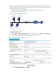

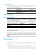
Table Of Contents
- Title page
- Contents
- Interface management configuration
- IP addressing configuration
- MAC address table configuration
- Layer 2 forwarding configuration
- Layer 2 forwarding overview
- Configuring general Layer 2 forwarding
- Configuring inline Layer 2 forwarding
- Configuring inter-VLAN Layer 2 forwarding
- Forward-type inline Layer 2 forwarding configuration example
- Blackhole-type inline Layer 2 forwarding configuration example
- Inter-VLAN Layer 2 forwarding configuration example
- VLAN configuration
- ARP configuration
- Gratuitous ARP configuration
- Proxy ARP configuration
- Layer 3 forwarding configuration
- NAT configuration
- Overview
- Configuring a NAT policy in the web interface
- Configuring NAT in the CLIs
- Configuration guidelines
- ALG configuration
- Static route configuration
- RIP configuration
- OSPF configuration
- BGP configuration
- Policy-based routing configuration
- Route displaying
- DNS configuration
- Overview
- Configuring DNS on the web interface
- Configuring DNS in the CLIs
- Troubleshooting IPv4 DNS configuration
- Support and other resources
- Index
103
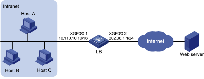
Figure 62 NAT network diagram
2. Configuration procedure
# Configure address pool 1.
<LB> system-view
[LB] nat address-group 1 202.38.1.2 202.38.1.3
# Configure ACL 2001, permitting only users from network segment 10.110.10.0/24 to access the
Internet.
[LB] acl number 2001
[LB-acl-basic-2001] rule permit source 10.110.10.0 0.0.0.255
[LB-acl-basic-2001] rule deny
[LB-acl-basic-2001] quit
# Associate address pool 1 and ACL 2001 with the outbound interface Ten-GigabitEthernet0/0.2.
[LB] interface Ten-GigabitEthernet 0/0.2
[LB-Ten-GigabitEthernet0/0.2] nat outbound 2001 address-group 1
[LB-Ten-GigabitEthernet0/0.2] quit
Common internal server configuration example
1. Network requirements
As shown in Figure 63, a c
ompany provides two web servers, one FTP server, and one SMTP server for
external users to access. The internal network address is 10.110.0.0/16. The internal address for the FTP
server is 10.110.10.3/16, for web server 1 is 10.110.10.1/16, for web server 2 is 10.110.10.2/16, and for
the SMTP server 10.110.10.4/16. The company has three public IP addresses ranging from
202.38.1.1/24 to 202.38.1.3/24. Specifically, the company has the following requirements:
• External hosts can access internal servers with public address 202.38.1.1/24.
• Port 8080 is used for web server 2.