
R3204P16-HP Load Balancing Module Network Management Configuration Guide-6PW101
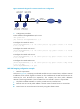
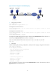
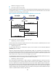
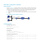
Table Of Contents
- Title page
- Contents
- Interface management configuration
- IP addressing configuration
- MAC address table configuration
- Layer 2 forwarding configuration
- Layer 2 forwarding overview
- Configuring general Layer 2 forwarding
- Configuring inline Layer 2 forwarding
- Configuring inter-VLAN Layer 2 forwarding
- Forward-type inline Layer 2 forwarding configuration example
- Blackhole-type inline Layer 2 forwarding configuration example
- Inter-VLAN Layer 2 forwarding configuration example
- VLAN configuration
- ARP configuration
- Gratuitous ARP configuration
- Proxy ARP configuration
- Layer 3 forwarding configuration
- NAT configuration
- Overview
- Configuring a NAT policy in the web interface
- Configuring NAT in the CLIs
- Configuration guidelines
- ALG configuration
- Static route configuration
- RIP configuration
- OSPF configuration
- BGP configuration
- Policy-based routing configuration
- Route displaying
- DNS configuration
- Overview
- Configuring DNS on the web interface
- Configuring DNS in the CLIs
- Troubleshooting IPv4 DNS configuration
- Support and other resources
- Index
104
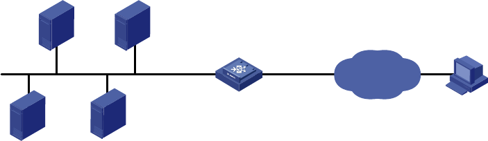
Figure 63 Network diagram for common internal server configuration
2. Configuration procedure
# Enter interface Ten-GigabitEthernet 0/0.2 view.
<LB> system-view
[LB] interface Ten-GigabitEthernet 0/0.2
# Configure the internal FTP server.
[LB-Ten-GigabitEthernet0/0.2] nat server protocol tcp global 202.38.1.1 21 inside
10.110.10.3 ftp
# Configure the internal web server 1.
[LB-Ten-GigabitEthernet0/0.2] nat server protocol tcp global 202.38.1.1 80 inside
10.110.10.1 www
# Configure the internal web server 2.
[LB-Ten-GigabitEthernet0/0.2] nat server protocol tcp global 202.38.1.1 8080 inside
10.110.10.2 www
# Configure the internal SMTP server.
[LB-Ten-GigabitEthernet0/0.2] nat server protocol tcp global 202.38.1.1 smtp inside
10.110.10.4 smtp
[LB-Ten-GigabitEthernet0/0.2] quit
NAT DNS mapping configuration example
1. Network requirements
As shown in Figure 64, a c
ompany provides Web and FTP services to external users, and has its internal
IP addresses on the network segment 10.110.0.0/16. The IP addresses of the Web and FTP servers are
10.110.10.1/16 and 10.110.10.2/16 respectively. The company has three public addresses
202.38.1.1/24 through 202.38.1.3/24. The DNS server is at 202.38.1.4/24. It is required that:
• The public IP address 202.38.1.2 is used to provide services to external users.
• External users can use the public address or domain name of internal servers to access them.
• Internal users can access the internal servers by using their domain names.
FTP server
10.110.10.3/16
Web server 1
10.110.10.1/16
Web server 2
10.110.10.2/16
SMTP server
10.110.10.4/16
Host
Internet
XGE0/0.1
10.110.10.10/16
XGE0/0.2
202.38.1.1/24
LB