
R3204P16-HP Load Balancing Module Network Management Configuration Guide-6PW101
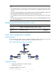
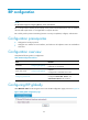
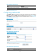
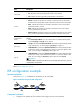
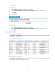
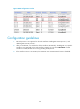
Table Of Contents
- Title page
- Contents
- Interface management configuration
- IP addressing configuration
- MAC address table configuration
- Layer 2 forwarding configuration
- Layer 2 forwarding overview
- Configuring general Layer 2 forwarding
- Configuring inline Layer 2 forwarding
- Configuring inter-VLAN Layer 2 forwarding
- Forward-type inline Layer 2 forwarding configuration example
- Blackhole-type inline Layer 2 forwarding configuration example
- Inter-VLAN Layer 2 forwarding configuration example
- VLAN configuration
- ARP configuration
- Gratuitous ARP configuration
- Proxy ARP configuration
- Layer 3 forwarding configuration
- NAT configuration
- Overview
- Configuring a NAT policy in the web interface
- Configuring NAT in the CLIs
- Configuration guidelines
- ALG configuration
- Static route configuration
- RIP configuration
- OSPF configuration
- BGP configuration
- Policy-based routing configuration
- Route displaying
- DNS configuration
- Overview
- Configuring DNS on the web interface
- Configuring DNS in the CLIs
- Troubleshooting IPv4 DNS configuration
- Support and other resources
- Index
121
Item Descri
p
tion
Work State
Set whether to allow the receiving/sending of RIP packets on the interface.
• On: Allows the receiving/sending of RIP packets on the interface.
• Off: Disallows the receiving/sending of RIP packets on the interface.
Version
Specify a RIP version for the interface.
• Default: Indicates the interface can send RIPv1 broadcasts and can receive RIPv1
broadcast and unicast packets, and RIPv2 broadcast, multicast, and unicast packets.
• RIPv1: Indicates the interface can send RIPv1 broadcasts, and can receive RIPv1
broadcasts and RIPv1 unicasts.
• RIPv2: Indicates the interface can send RIPv2 multicasts and can receive RIPv2
unicasts, broadcasts and multicasts.
• RIPv2 broadcast: Indicates the interface can send RIPv2 broadcasts and can receive
RIPv1 unicasts, and broadcasts, and RIPv2 broadcasts, multicasts and unicasts.
Authentication
Mode
Set the authentication mode and parameters for authenticating RIP packets on a RIPv2
interface.
• If the Authentication Mode is null, the interface does not authenticate RIP packets,
and the Key String and Key ID are not required.
• If Simple is specified for Authentication Mode, the interface authenticates RIP packets
using simple text key. You must configure a Key String in simple text.
• If MD5 RFC2453 is specified for Authentication Mode, the interface adopts the MD5
authentication mode, and the authentication packet is in the format defined in RFC
2453. You must configure a Key String in MD5 cipher text.
• If MD5 RFC2082 is specified for Authentication Mode, the interface adopts the MD5
authentication mode, and the authentication packet is in the format defined in RFC
2082. You must configure a Key String in MD5 cipher text and a Key ID.
IMPORTANT:
If Default or RIPv1 is specified as the RIP version, the authentication information you have
configured does not take effect.
Key String
Key ID
Return to RIP configuration task list.
RIP configuration example
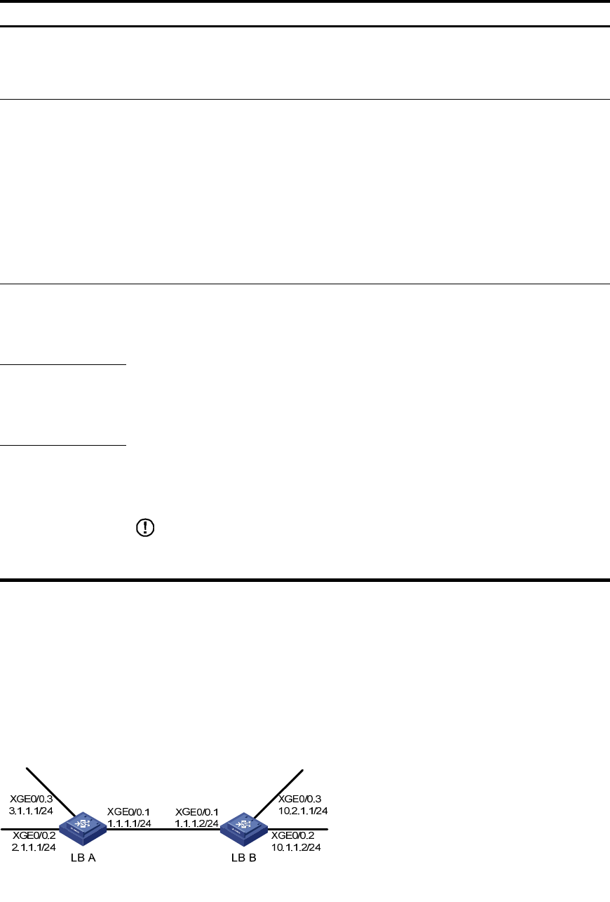
Network requirements
As shown in Figure 77, enable RIP on all interfaces on LB A and LB B.
Figure 77 Network diagram for RIP configuration
Configuration procedure
1. Configure an IP address for each interface and configure security zones (omitted).