
R3204P16-HP Load Balancing Module Network Management Configuration Guide-6PW101
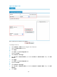
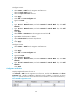
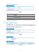
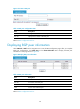
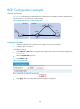
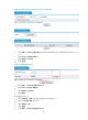
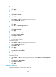

Table Of Contents
- Title page
- Contents
- Interface management configuration
- IP addressing configuration
- MAC address table configuration
- Layer 2 forwarding configuration
- Layer 2 forwarding overview
- Configuring general Layer 2 forwarding
- Configuring inline Layer 2 forwarding
- Configuring inter-VLAN Layer 2 forwarding
- Forward-type inline Layer 2 forwarding configuration example
- Blackhole-type inline Layer 2 forwarding configuration example
- Inter-VLAN Layer 2 forwarding configuration example
- VLAN configuration
- ARP configuration
- Gratuitous ARP configuration
- Proxy ARP configuration
- Layer 3 forwarding configuration
- NAT configuration
- Overview
- Configuring a NAT policy in the web interface
- Configuring NAT in the CLIs
- Configuration guidelines
- ALG configuration
- Static route configuration
- RIP configuration
- OSPF configuration
- BGP configuration
- Policy-based routing configuration
- Route displaying
- DNS configuration
- Overview
- Configuring DNS on the web interface
- Configuring DNS in the CLIs
- Troubleshooting IPv4 DNS configuration
- Support and other resources
- Index
140
BGP Configuration example
Network requirements
In Figure 99 are all BGP devices. Between Device A and Device B is an eBGP connection. iBGP speakers
Device B, Device C, and Device D are fully meshed.
Figure 99 Network diagram for BGP configuration
Configuration procedure
1. Configure IP addresses for interfaces and configure security zones (omitted).
2. Configure iBGP connections.
# Configure Device B.
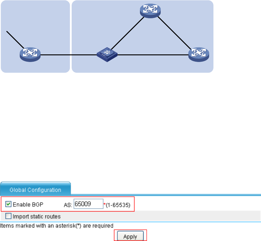
• Select Network > BGP from the navigation tree of Device B and make the following configurations
in Figure 100.
• Sel
ect the Enable BGP check box.
• Type 65009 for AS.
Figure 100 Enable BGP
• Click Apply. After you enable BGP, the following figure is displayed.
Device A
AS 65008
XGE0/0.1
200.1.1.1/24
Device C
Device B
(LB)
Device D
AS 65009
GE0/0
8.1.1.1/8
GE0/1
200.1.1.2/24
XGE0/0.3
9.1.1.1/24
XGE0/0.2
9.1.3.1/24
GE0/2
9.1.3.2/24
GE0/1
9.1.2.1/24
GE0/1
9.1.2.2/24
GE0/0
9.1.1.2/24