
R3204P16-HP Load Balancing Module Network Management Configuration Guide-6PW101
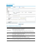

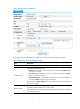
Table Of Contents
- Title page
- Contents
- Interface management configuration
- IP addressing configuration
- MAC address table configuration
- Layer 2 forwarding configuration
- Layer 2 forwarding overview
- Configuring general Layer 2 forwarding
- Configuring inline Layer 2 forwarding
- Configuring inter-VLAN Layer 2 forwarding
- Forward-type inline Layer 2 forwarding configuration example
- Blackhole-type inline Layer 2 forwarding configuration example
- Inter-VLAN Layer 2 forwarding configuration example
- VLAN configuration
- ARP configuration
- Gratuitous ARP configuration
- Proxy ARP configuration
- Layer 3 forwarding configuration
- NAT configuration
- Overview
- Configuring a NAT policy in the web interface
- Configuring NAT in the CLIs
- Configuration guidelines
- ALG configuration
- Static route configuration
- RIP configuration
- OSPF configuration
- BGP configuration
- Policy-based routing configuration
- Route displaying
- DNS configuration
- Overview
- Configuring DNS on the web interface
- Configuring DNS in the CLIs
- Troubleshooting IPv4 DNS configuration
- Support and other resources
- Index

8
To do… Use the command… Remarks
Enter system view system-view —
Enter Ethernet interface
view
interface interface-type
interface-number
—
Change the description
of the interface
description text
Optional
By default, the description of an interface is interface
name Interface. For example, Ethernet1/1 Interface.
Set the duplex mode duplex { auto | full | half }
Optional
By default, full for a 10-GE interface, and auto for
other Ethernet interfaces
Optical interfaces do not support the half keyword.
Set the port speed
speed { 10 | 100 | 1000 |
auto }
Optional
Optical interfaces do not support the 10 or 100
keyword.
By default, an Ethernet interface negotiates a speed
with its peer.
Shut down the Ethernet
interface
shutdown
Optional
By default, an Ethernet interface is in up state.
To bring up an Ethernet interface, use the undo
shutdown command.
Ethernet subinterfaces fall into two categories: Layer 2 Ethernet subinterfaces and Layer 3 subinterfaces.
• Layer 2 Ethernet subinterface enables Layer 2 packets to be forwarded across VLANs. By
configuring Layer 2 Ethernet subinterfaces for VLANs, you can forward Layer 2 Ethernet packets
across VLANs through the corresponding Layer 2 Ethernet subinterfaces. Layer 2 Ethernet
subinterfaces are usually used when LB modules are used on network devices.
• Layer 3 Ethernet subinterface enables Layer 3 Ethernet interfaces to identify packets by VLANs. By
configuring multiple subinterfaces on an Ethernet interface, you can have packets of different
VLANs forwarded through their corresponding subinterfaces, thus achieving flexibility.
Follow these steps to configure an Ethernet subinterface:
To do… Use the command… Remarks
Enter system view system-view —
Create an Ethernet
subinterface
interface interface-type
interface-number.subnumber
Required
This command also leads you to Ethernet
subinterface view.
Change the description
of the subinterface
description text
Optional
By default, the description is interface name
Interface. For example, GE0/3.1 Interface.
Shut down the Ethernet
subinterface
shutdown
Optional
By default, an Ethernet subinterface is in up state.