
R3204P16-HP Load Balancing Module Network Management Configuration Guide-6PW101
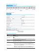
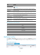
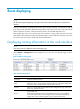
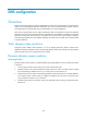
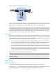
Table Of Contents
- Title page
- Contents
- Interface management configuration
- IP addressing configuration
- MAC address table configuration
- Layer 2 forwarding configuration
- Layer 2 forwarding overview
- Configuring general Layer 2 forwarding
- Configuring inline Layer 2 forwarding
- Configuring inter-VLAN Layer 2 forwarding
- Forward-type inline Layer 2 forwarding configuration example
- Blackhole-type inline Layer 2 forwarding configuration example
- Inter-VLAN Layer 2 forwarding configuration example
- VLAN configuration
- ARP configuration
- Gratuitous ARP configuration
- Proxy ARP configuration
- Layer 3 forwarding configuration
- NAT configuration
- Overview
- Configuring a NAT policy in the web interface
- Configuring NAT in the CLIs
- Configuration guidelines
- ALG configuration
- Static route configuration
- RIP configuration
- OSPF configuration
- BGP configuration
- Policy-based routing configuration
- Route displaying
- DNS configuration
- Overview
- Configuring DNS on the web interface
- Configuring DNS in the CLIs
- Troubleshooting IPv4 DNS configuration
- Support and other resources
- Index
148
Route displaying
NOTE:
The LB module supports displaying routing information both in the web interface and command line
interface.
Routing in the Internet is achieved through routers. Upon receiving a packet, a router finds an optimal
route based on the destination address and forwards the packet to the next router in the path until the
packet reaches the last router, which forwards the packet to the intended destination host.
Routing tables play a key role in routing. Each router maintains a routing table, and each entry in the
table specifies which physical interface a packet destined for a certain destination should go out to reach
the next hop (the next router) or the directly connected destination.
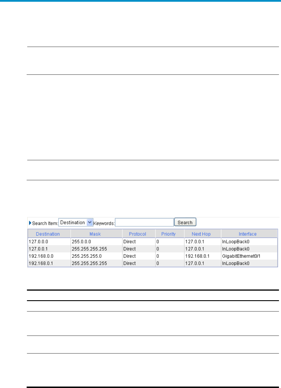
Displaying routing information in the web interface
NOTE:
Only active routes are displayed on the route display page.
Select Network > Routing Info from the navigation tree to enter the route display page, as shown
in Figure 108.
Figure 108 Route display page
Table 36 Route display items
Item Remarks
Destination
Destination address/network
Mask
Together with the destination address, the mask specifies the address of the
destination network. A logical AND operation between the destination address and
the network mask yields the address of the destination network.
Protocol
Routes in a routing table can be divided into three categories by origin: static route,
direct route, and dynamic route.
Priority
Priority of the route
Routes to the same destination but having different next hops may have different
priorities and be found by various routing protocols or manually configured. The
optimal route is the one with the highest priority (with the smallest value).