
R3204P16-HP Load Balancing Module Network Management Configuration Guide-6PW101
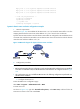
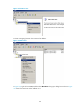
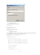
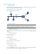
Table Of Contents
- Title page
- Contents
- Interface management configuration
- IP addressing configuration
- MAC address table configuration
- Layer 2 forwarding configuration
- Layer 2 forwarding overview
- Configuring general Layer 2 forwarding
- Configuring inline Layer 2 forwarding
- Configuring inter-VLAN Layer 2 forwarding
- Forward-type inline Layer 2 forwarding configuration example
- Blackhole-type inline Layer 2 forwarding configuration example
- Inter-VLAN Layer 2 forwarding configuration example
- VLAN configuration
- ARP configuration
- Gratuitous ARP configuration
- Proxy ARP configuration
- Layer 3 forwarding configuration
- NAT configuration
- Overview
- Configuring a NAT policy in the web interface
- Configuring NAT in the CLIs
- Configuration guidelines
- ALG configuration
- Static route configuration
- RIP configuration
- OSPF configuration
- BGP configuration
- Policy-based routing configuration
- Route displaying
- DNS configuration
- Overview
- Configuring DNS on the web interface
- Configuring DNS in the CLIs
- Troubleshooting IPv4 DNS configuration
- Support and other resources
- Index
166
DNS Proxy configuration example
1. Network requirements
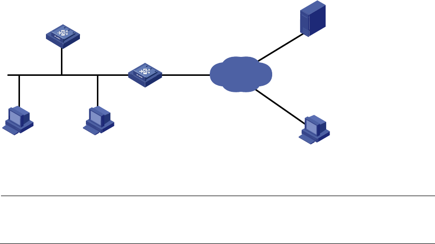
As shown in Figure 128,
specify LB A as the DNS server of LB B (the DNS client). LB A acts as a DNS
proxy. The IP address of the real DNS server is 4.1.1.1.
LB B implements domain name resolution through LB A.
Figure 128 Network diagram for DNS proxy
2. Configuration procedure
NOTE:
Before performing the following configuration, assume that LB A, the DNS server, and the host are
reachable to each other and the IP addresses of the interfaces are configured as shown in Figure 128.
a. Configure the DNS server
This configuration may vary with different DNS servers. When a Windows server 2000 PC acts as the
DNS server, see “Dynamic domain name resolution configuration example” f
or related configuration
information.
b. Configure the DNS proxy
# S p e c i f y t h e D N S s e r v e r 4 .1.1.1.
<LB A> system-view
[LB A] dns server 4.1.1.1
# Enable DNS proxy.
[LB A] dns proxy enable
c. Configure the DNS client
# Enable the domain name resolution function.
<LB B> system-view
[LB B] dns resolve
# Specify the DNS server 2.1.1.2.
[LB B] dns server 2.1.1.2
d. Configuration verification
# Execute the ping host.com command on LB B to verify that the communication between LB B and the
host is normal and that the corresponding destination IP address is 3.1.1.1.
DNS proxy
(LB A)
DNS server
DNS client
(LB B)
IP network
Host
2.1.1.2/24
1.1.1.1/24
2.1.1.1/24
4.1.1.1/24
3.1.1.1/24
Host.com