
R3204P16-HP Load Balancing Module Network Management Configuration Guide-6PW101
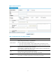
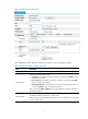
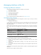
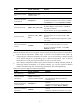
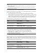
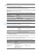
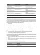
Table Of Contents
- Title page
- Contents
- Interface management configuration
- IP addressing configuration
- MAC address table configuration
- Layer 2 forwarding configuration
- Layer 2 forwarding overview
- Configuring general Layer 2 forwarding
- Configuring inline Layer 2 forwarding
- Configuring inter-VLAN Layer 2 forwarding
- Forward-type inline Layer 2 forwarding configuration example
- Blackhole-type inline Layer 2 forwarding configuration example
- Inter-VLAN Layer 2 forwarding configuration example
- VLAN configuration
- ARP configuration
- Gratuitous ARP configuration
- Proxy ARP configuration
- Layer 3 forwarding configuration
- NAT configuration
- Overview
- Configuring a NAT policy in the web interface
- Configuring NAT in the CLIs
- Configuration guidelines
- ALG configuration
- Static route configuration
- RIP configuration
- OSPF configuration
- BGP configuration
- Policy-based routing configuration
- Route displaying
- DNS configuration
- Overview
- Configuring DNS on the web interface
- Configuring DNS in the CLIs
- Troubleshooting IPv4 DNS configuration
- Support and other resources
- Index

11
To do… Use the command… Remarks
Set the broadcast
suppression threshold ratio
broadcast-suppression ratio
Optional
By default, Ethernet interfaces do not
suppress broadcast traffic.
Set the multicast
suppression threshold ratio
multicast-suppression ratio
Optional
By default, Ethernet interfaces do not
suppress multicast traffic.
Set the unknown unicast
suppression threshold ratio
unicast-suppression ratio
Optional
By default, Ethernet interfaces do not
suppress unknown unicast traffic.
2. Setting the MDI mode of an Ethernet interface
NOTE:
Optical interfaces do not support the MDI mode setting.
You can use both crossover and straight-through Ethernet cables to connect copper Ethernet interfaces.
To accommodate these two types of cables, a copper Ethernet interface can operate in one of the
following three Medium Dependent Interface (MDI) modes:
• Across mode
• Normal mode
• Auto mode
A copper Ethernet interface uses an RJ-45 connector, which comprises eight pins, each playing a
dedicated role. For example, pins 1 and 2 transmit signals, and pins 3 and 6 receive signals. You can
change their role by setting the MDI mode of the interface:
• In normal mode, pins 1 and 2 are transmit pins, and pins 3 and 6 are receive pins.
• In across mode, pins 1 and 2 are receive pins, and pins 3 and 6 are transmit pins.
• In auto mode, the interface negotiates pin roles with its peer.
To enable the interface to communicate with its peer, ensure that its transmit pins are connected to the
remote receive pins. If the interface can detect the connection cable type, set the interface in auto MDI
mode. If not, set its MDI mode as follows:
• When a straight-through cable is used, set the interface to work in the MDI mode different than its
peer.
• When a crossover cable is used, set the interface to work in the same MDI mode as its peer, or set
either end to work in auto mode.
Follow these steps to set the MDI mode of an Ethernet interface:
To do… Use the command… Remarks
Enter system view system-view —
Enter Ethernet interface view
interface interface-type
interface-number
—