
R3204P16-HP Load Balancing Module Network Management Configuration Guide-6PW101
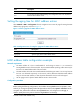
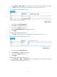
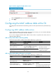
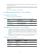
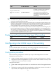
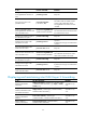
Table Of Contents
- Title page
- Contents
- Interface management configuration
- IP addressing configuration
- MAC address table configuration
- Layer 2 forwarding configuration
- Layer 2 forwarding overview
- Configuring general Layer 2 forwarding
- Configuring inline Layer 2 forwarding
- Configuring inter-VLAN Layer 2 forwarding
- Forward-type inline Layer 2 forwarding configuration example
- Blackhole-type inline Layer 2 forwarding configuration example
- Inter-VLAN Layer 2 forwarding configuration example
- VLAN configuration
- ARP configuration
- Gratuitous ARP configuration
- Proxy ARP configuration
- Layer 3 forwarding configuration
- NAT configuration
- Overview
- Configuring a NAT policy in the web interface
- Configuring NAT in the CLIs
- Configuration guidelines
- ALG configuration
- Static route configuration
- RIP configuration
- OSPF configuration
- BGP configuration
- Policy-based routing configuration
- Route displaying
- DNS configuration
- Overview
- Configuring DNS on the web interface
- Configuring DNS in the CLIs
- Troubleshooting IPv4 DNS configuration
- Support and other resources
- Index
25
• Select Network > MAC > MAC from the navigation tree to enter the MAC address entry list page,
click Add, and make the following configurations on the page as shown in Figure 12.
Figure 12 Create a static MAC address entry
• Enter MAC address 000f-e235-dc71.
• Select static in the Type drop-down list.
• Select 1 in the VLAN drop-down list.
• Select Ten-GigabitEthernet0/0 in the Port drop-down list.
• Click Apply.
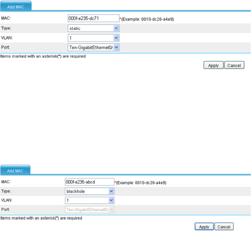
# Create a blackhole MAC address entry.
• Click Add, and make the following configurations on the page as shown in Figure 13.
Figure 13 Create a blackhole MAC address entry
• Enter MAC address 000f-e235-abcd.
• Select blackhole in the Type drop-down list.
• Select 1 in the VLAN drop-down list.
• Click Apply.
# Set the aging time for MAC address entries.
• Select Network > MAC > Configuration from the navigation tree, and make the following
configuration on the page shown in Figure 14.