
R3204P16-HP Load Balancing Module Network Management Configuration Guide-6PW101
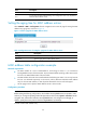
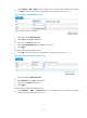
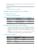
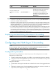
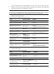
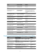
Table Of Contents
- Title page
- Contents
- Interface management configuration
- IP addressing configuration
- MAC address table configuration
- Layer 2 forwarding configuration
- Layer 2 forwarding overview
- Configuring general Layer 2 forwarding
- Configuring inline Layer 2 forwarding
- Configuring inter-VLAN Layer 2 forwarding
- Forward-type inline Layer 2 forwarding configuration example
- Blackhole-type inline Layer 2 forwarding configuration example
- Inter-VLAN Layer 2 forwarding configuration example
- VLAN configuration
- ARP configuration
- Gratuitous ARP configuration
- Proxy ARP configuration
- Layer 3 forwarding configuration
- NAT configuration
- Overview
- Configuring a NAT policy in the web interface
- Configuring NAT in the CLIs
- Configuration guidelines
- ALG configuration
- Static route configuration
- RIP configuration
- OSPF configuration
- BGP configuration
- Policy-based routing configuration
- Route displaying
- DNS configuration
- Overview
- Configuring DNS on the web interface
- Configuring DNS in the CLIs
- Troubleshooting IPv4 DNS configuration
- Support and other resources
- Index

31
To do… Use the command…
Remarks
Assign an interface to the
inline Layer 2 forwarding
entry
port inline-interfaces id
Required
By default, the interface does not belong to
any inline Layer 2 forwarding entry.
Two interfaces must be assigned to the
forward-type inline forwarding entry while
one interface is required for the reflect or
blackhole type.
CAUTION:
•
An interface can only belong to one inline forwarding entry, and the last configured port inline-interfaces id
command on an Ethernet interface takes effect.
• Subinterfaces can be assigned to inline Layer 2 forwarding entries. To make these entries take effect, the main
interface must be assigned to the VLAN of which the ID is used as the subinterface number. For example, if the
subinterface GigabitEthernet 0/1.2 is assigned to an inline forwarding entry, the interface GigabitEthernet 0/1
must be assigned to VLAN 2 so that the inline Layer 2 forwarding can be implemented.
• If an interface and its subinterface are assigned to different inline forwarding entries, the forwarding entry with
the main interface takes precedence. For example, the interfaces GigabitEthernet 0/1 and GigabitEthernet 0/2
are assigned to one inline forwarding entry, and the subinterfaces GigabitEthernet 0/1.2 and GigabitEthernet
0/2.3 are assigned to another forwarding entry; then the data received from GigabitEthernet 0/1 is forwarded
through the interface GigabitEthernet 0/2, and vise versa.
Displaying and maintaining inline Layer 2 forwarding
To do… Use the command…
Remarks
Display inline Layer 2 forwarding configuration
display inline-interfaces Available in any view
Configuring inter-VLAN Layer 2 forwarding
NOTE:
For more information about inter-VLAN Layer 2 forwarding configuration commands, see Layer 2
Forwarding Commands in
Network Management Command Reference
.
Configuration procedure
Perform the following configurations to achieve Layer 2 Layer 2 forwarding between two VLANs.
Configure the ports of the switch.
• Create two VLANs. Assign the ingress port of traffic to one VLAN and the egress port to the other.
• Configure the switch’s Ten-GigabitEthernet port that connects to the LB module as a trunk port and
configure the trunk port to join these two VLANs.
Configure the LB module.
• Create VLAN X and assign the LB module to it. Packets from the switch will be tagged with VLAN
X.
• Configure the operating mode of the Ten-GigabitEthernet interface that connects to the switch as
Layer 2 mode, and configure the link type of the interface as trunk.