
R3204P16-HP Load Balancing Module Network Management Configuration Guide-6PW101
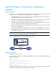
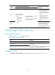
Table Of Contents
- Title page
- Contents
- Interface management configuration
- IP addressing configuration
- MAC address table configuration
- Layer 2 forwarding configuration
- Layer 2 forwarding overview
- Configuring general Layer 2 forwarding
- Configuring inline Layer 2 forwarding
- Configuring inter-VLAN Layer 2 forwarding
- Forward-type inline Layer 2 forwarding configuration example
- Blackhole-type inline Layer 2 forwarding configuration example
- Inter-VLAN Layer 2 forwarding configuration example
- VLAN configuration
- ARP configuration
- Gratuitous ARP configuration
- Proxy ARP configuration
- Layer 3 forwarding configuration
- NAT configuration
- Overview
- Configuring a NAT policy in the web interface
- Configuring NAT in the CLIs
- Configuration guidelines
- ALG configuration
- Static route configuration
- RIP configuration
- OSPF configuration
- BGP configuration
- Policy-based routing configuration
- Route displaying
- DNS configuration
- Overview
- Configuring DNS on the web interface
- Configuring DNS in the CLIs
- Troubleshooting IPv4 DNS configuration
- Support and other resources
- Index
35
Inter-VLAN Layer 2 forwarding configuration
example
Network requirements
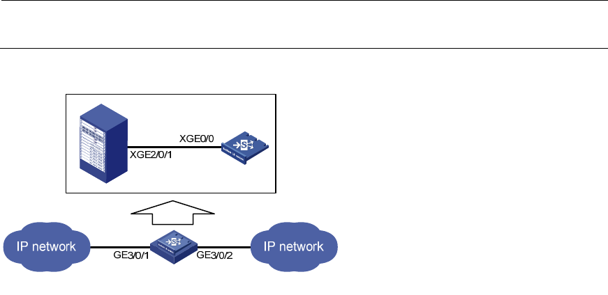
As shown in Figure 16, traffic between GigabitEthernet 3/0/1 and GigabitEthernet 3/0/2 is filtered by
a LB module, and inter-VLAN Layer 2 forwarding needs to be configured.
• Ten-GigabitEthernet 2/0/1 of the switch connects to Ten-GigabitEthernet 0/0 of the LB module.
Configure the link type of the two interfaces as trunk.
• Configure the operating mode of Ten-GigabitEthernet 2/0/1 as Layer 2. Assign the port to VLAN
102, VLAN 103 and VLAN 1000. The default VLAN of the port is VLAN 1000.
• Configure the operating mode of GigabitEthernet 3/0/1 and GigabitEthernet 3/0/2 of the switch
as access. Assign them to VLAN 102 and VLAN 103 respectively.
• Configure the operating mode of Ten-GigabitEthernet 0/0 as Layer 2. Assign the port to VLAN 102,
VLAN 103, and VLAN 1000.
• Create two subinterfaces Ten-GigabitEthernet 0/0.102 and Ten-GigabitEthernet 0/0.103 for
Ten-GigabitEthernet 0/0. Configure their operating mode as Layer 2 and the link type as access.
Assign them to VLAN 1000.
NOTE:
The VLAN 1000 on the switch and the LB module is locally significant.
Figure 16 Network diagram for inter-VLAN Layer 2 forwarding
Configuration Procedure
Configure the ports on the switch.
# Create VLAN 102 and VLAN 103. Assign GigabitEthernet 3/0/1 to VLAN 102 and GigabitEthernet
3/0/2 to VLAN 103.
<Sysname> system-view
[Sysname] vlan 102
[Sysname-vlan102] port gigabitethernet 3/0/1
[Sysname-vlan102] vlan 103
[Sysname-vlan103] port gigabitethernet 3/0/2
[Sysname-vlan103] quit
# Configure the link type of Ten-GigabitEthernet 2/0/1 as trunk and assign the trunk port to VLAN 102,
VLAN 103, and VLAN 1000. VLAN 1000 is the default VLAN.