
R3204P16-HP Load Balancing Module Network Management Configuration Guide-6PW101
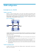
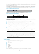
Table Of Contents
- Title page
- Contents
- Interface management configuration
- IP addressing configuration
- MAC address table configuration
- Layer 2 forwarding configuration
- Layer 2 forwarding overview
- Configuring general Layer 2 forwarding
- Configuring inline Layer 2 forwarding
- Configuring inter-VLAN Layer 2 forwarding
- Forward-type inline Layer 2 forwarding configuration example
- Blackhole-type inline Layer 2 forwarding configuration example
- Inter-VLAN Layer 2 forwarding configuration example
- VLAN configuration
- ARP configuration
- Gratuitous ARP configuration
- Proxy ARP configuration
- Layer 3 forwarding configuration
- NAT configuration
- Overview
- Configuring a NAT policy in the web interface
- Configuring NAT in the CLIs
- Configuration guidelines
- ALG configuration
- Static route configuration
- RIP configuration
- OSPF configuration
- BGP configuration
- Policy-based routing configuration
- Route displaying
- DNS configuration
- Overview
- Configuring DNS on the web interface
- Configuring DNS in the CLIs
- Troubleshooting IPv4 DNS configuration
- Support and other resources
- Index
37
VLAN configuration
Introduction to VLAN
VLAN overview
Ethernet is a network technology based on the Carrier Sense Multiple Access/Collision Detect
(CSMA/CD) mechanism. As the medium is shared, collisions and excessive broadcasts are common on
Ethernet networks. To address the issue, virtual LAN (VLAN) was introduced to break a LAN down into
separate VLANs. VLANs are isolated from each other at Layer 2. A VLAN is a bridging domain, and all
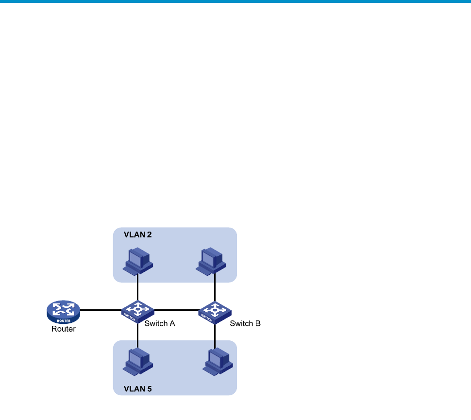
broadcast traffic is contained within it, as shown in Figure 17.
Figure 17 A VLAN diagram
A VLAN is logically divided on an organizational basis rather than on a physical basis. For example, all
workstations and servers used by a particular workgroup can be connected to the same LAN, regardless
of their physical locations.
VLAN technology delivers the following benefits:
• Confining broadcast traffic within individual VLANs. This reduces bandwidth waste and improves
network performance.
• Improving LAN security. By assigning user groups to different VLANs, you can isolate them at Layer
2. To enable communication between VLANs, routers or Layer 3 switches are required.
• Flexible virtual workgroup creation. As users from the same workgroup can be assigned to the same
VLAN regardless of their physical locations, network construction and maintenance is much easier
and more flexible.
VLAN fundamentals
To enable a network device to identify frames of different VLANs, a VLAN tag field is inserted into the
data link layer encapsulation.