
R3204P16-HP Load Balancing Module Network Management Configuration Guide-6PW101
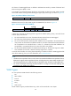
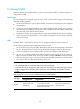
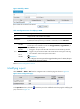
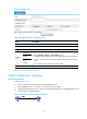
Table Of Contents
- Title page
- Contents
- Interface management configuration
- IP addressing configuration
- MAC address table configuration
- Layer 2 forwarding configuration
- Layer 2 forwarding overview
- Configuring general Layer 2 forwarding
- Configuring inline Layer 2 forwarding
- Configuring inter-VLAN Layer 2 forwarding
- Forward-type inline Layer 2 forwarding configuration example
- Blackhole-type inline Layer 2 forwarding configuration example
- Inter-VLAN Layer 2 forwarding configuration example
- VLAN configuration
- ARP configuration
- Gratuitous ARP configuration
- Proxy ARP configuration
- Layer 3 forwarding configuration
- NAT configuration
- Overview
- Configuring a NAT policy in the web interface
- Configuring NAT in the CLIs
- Configuration guidelines
- ALG configuration
- Static route configuration
- RIP configuration
- OSPF configuration
- BGP configuration
- Policy-based routing configuration
- Route displaying
- DNS configuration
- Overview
- Configuring DNS on the web interface
- Configuring DNS in the CLIs
- Troubleshooting IPv4 DNS configuration
- Support and other resources
- Index
38
The format of VLAN-tagged frames is defined in IEEE 802.1Q issued by Institute of Electrical and
Electronics Engineers (IEEE) in 1999.
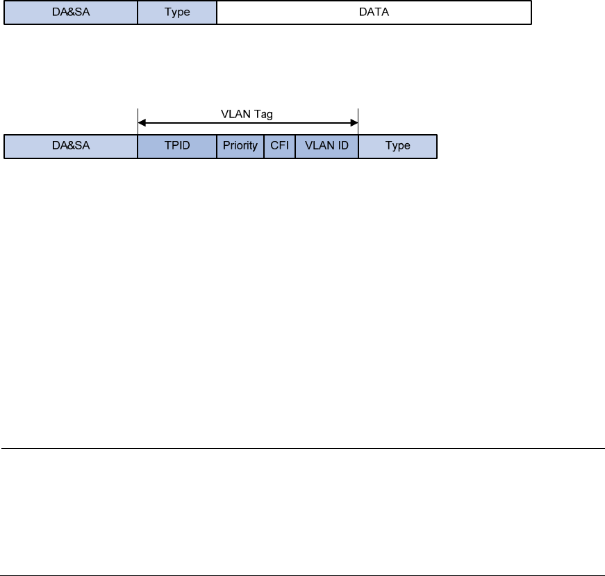
In the header of a traditional Ethernet data frame, the field after the destination MAC address and the
source MAC address is the Type field indicating the upper layer protocol type, as shown in Figure 18.
Figure 18 Traditional Et
hernet frame format
IEEE 802.1Q inserts a four-byte VLAN tag after the DA&SA field, as shown in Figure 19.
Figure 19 Position and format of VLAN tag
A VLAN tag comprises the following fields: tag protocol identifier (TPID), priority, canonical format
indicator (CFI), and VLAN ID.
• The 16-bit TPID field with a value of 0x8100 indicates that the frame is VLAN tagged.
• The 3-bit priority field indicates the 802.1p priority of the frame.
• The 1-bit CFI field specifies whether the MAC addresses are encapsulated in the standard format
when packets are transmitted across different media. A value of 0 indicates that the MAC addresses
are encapsulated in the standard format. A value of 1 indicates that the MAC addresses are
encapsulated in non-standard format. The value of the field is 0 by default.
• The 12-bit VLAN ID field identifies the VLAN the frame belongs to. The VLAN ID range is 0 to 4095.
As 0 and 4095 are reserved, a VLAN ID actually ranges from 1 to 4094.
A network device handles an incoming frame depending on whether the frame is VLAN tagged and the
value of the VLAN tag, if any. For more information, see “Port-based VLAN.”
NOTE:
• The Ethernet II encapsulation format is used in this section. Besides the Ethernet II encapsulation format,
Ethernet also supports other encapsulation formats, includin
g
802.2 LLC, 802.2 SNAP, and 802.3 raw.
The VLAN tag fields are also added to frames encapsulated in these formats for VLAN identification.
• For a frame with multiple VLAN tags, the device handles it according to its outer-most VLAN tag and
transmits its inner VLAN tags as payload.
VLAN types
You can implement VLANs based on the following criteria:
• Port
• MAC address
• Protocol
• IP subnet
• Policy
• Other criteria
The LB modules support port-based VLAN only, which will be introduced in this chapter.