
R3204P16-HP Load Balancing Module Network Management Configuration Guide-6PW101
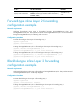
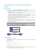
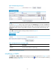
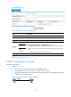
Table Of Contents
- Title page
- Contents
- Interface management configuration
- IP addressing configuration
- MAC address table configuration
- Layer 2 forwarding configuration
- Layer 2 forwarding overview
- Configuring general Layer 2 forwarding
- Configuring inline Layer 2 forwarding
- Configuring inter-VLAN Layer 2 forwarding
- Forward-type inline Layer 2 forwarding configuration example
- Blackhole-type inline Layer 2 forwarding configuration example
- Inter-VLAN Layer 2 forwarding configuration example
- VLAN configuration
- ARP configuration
- Gratuitous ARP configuration
- Proxy ARP configuration
- Layer 3 forwarding configuration
- NAT configuration
- Overview
- Configuring a NAT policy in the web interface
- Configuring NAT in the CLIs
- Configuration guidelines
- ALG configuration
- Static route configuration
- RIP configuration
- OSPF configuration
- BGP configuration
- Policy-based routing configuration
- Route displaying
- DNS configuration
- Overview
- Configuring DNS on the web interface
- Configuring DNS in the CLIs
- Troubleshooting IPv4 DNS configuration
- Support and other resources
- Index
41
Figure 20 VLAN configuration page
NOTE:
A
s shown in Figure 20, when you type a VLAN range in the VLAN Range box and then click Select, the
table below lists information about all VLANs within this ran
g
e, which makes the operation much easier
w
hen the LB module contains a large number of VLANs. To remove all VLANs within this range, click
Remove.
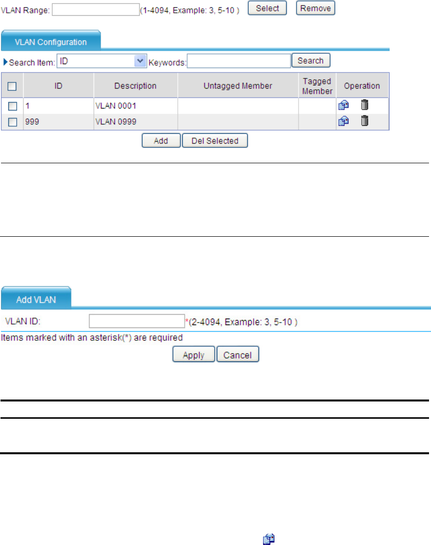
Click Add to enter the page for creating a VLAN, as shown in Figure 21.
Figure 21 Create a VLAN
Table 7 Configuration items of creating a VLAN
Item Descri
p
tion
VLAN ID
ID of the VLAN to be created.
You can create a VLAN or a VLAN range.
Return to VLAN configuration task list.
Modifying a VLAN
Select Network > VLAN > VLAN from the navigation tree to enter the page as shown in Figure 20. In the
Operation column for the VLAN you want to modify, click the icon to enter the page for modifying
the VLAN, as shown in Figure 22.