
R3204P16-HP Load Balancing Module Network Management Configuration Guide-6PW101
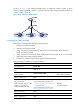
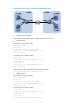
Table Of Contents
- Title page
- Contents
- Interface management configuration
- IP addressing configuration
- MAC address table configuration
- Layer 2 forwarding configuration
- Layer 2 forwarding overview
- Configuring general Layer 2 forwarding
- Configuring inline Layer 2 forwarding
- Configuring inter-VLAN Layer 2 forwarding
- Forward-type inline Layer 2 forwarding configuration example
- Blackhole-type inline Layer 2 forwarding configuration example
- Inter-VLAN Layer 2 forwarding configuration example
- VLAN configuration
- ARP configuration
- Gratuitous ARP configuration
- Proxy ARP configuration
- Layer 3 forwarding configuration
- NAT configuration
- Overview
- Configuring a NAT policy in the web interface
- Configuring NAT in the CLIs
- Configuration guidelines
- ALG configuration
- Static route configuration
- RIP configuration
- OSPF configuration
- BGP configuration
- Policy-based routing configuration
- Route displaying
- DNS configuration
- Overview
- Configuring DNS on the web interface
- Configuring DNS in the CLIs
- Troubleshooting IPv4 DNS configuration
- Support and other resources
- Index

52
To do... Use the command
Remarks
Assign ports to each secondary
VLAN and ensure that at least one
port in a secondary VLAN takes the
secondary VLAN as its PVID
• For access ports:
For the configuration procedure,
see Assigning an access port to a VLAN.”
• For hybrid ports:
For the configuration procedure, see
“Assigning a hybrid port to a VLAN.”
Required
Use either approach.
Return to system view quit —
Associate the isolate-user-VLAN
with the specified secondary
VLANs
isolate-user-vlan isolate-user-vlan-id
secondary secondary-vlan-id [ to
secondary-vlan-id ]
Required
NOTE:
A
fter associatin
g
an isolate-user-VLAN with the specified secondary VLANs, you cannot add/remove a
port to/from each involved VLAN or remove each involved VLAN. To do that, you must cancel the
association first.
Displaying and maintaining isolate-user-VLAN
To do... Use the command...
Remarks
Display the mapping between an isolate-user-VLAN
and its secondary VLAN(s)
display isolate-user-vlan
[ isolate-user-vlan-id ]
Available in any view
Isolate-user-VLAN configuration example
1. Network requirements
As shown in Figure 28,
• C
onnect the device to downstream devices LB A and LB B.
• Configure VLAN 5 on LB A as an isolate-user-VLAN, assign uplink port Ten-GigabitEthernet 0/0.5
to VLAN 5, and associate VLAN 5 with secondary VLANs VLAN 2 and VLAN 3. Assign
Ten-GigabitEthernet 0/0.2 to VLAN 2 and Ten-GigabitEthernet 0/0.1 to VLAN 3.
• Configure VLAN 6 on LB B as an isolate-user-VLAN, assign uplink port Ten-GigabitEthernet 0/0.5
to VLAN 6, and associate VLAN 6 with secondary VLANs VLAN 3 and VLAN 4. Assign
Ten-GigabitEthernet 0/0.3 to VLAN 3 and Ten-GigabitEthernet 0/0.4 to VLAN 4.
• As far as the device is concerned, LB A only has VLAN 5 and LB B only has VLAN 6.