
R3204P16-HP Load Balancing Module Network Management Configuration Guide-6PW101

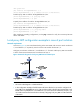
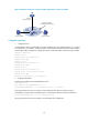
Table Of Contents
- Title page
- Contents
- Interface management configuration
- IP addressing configuration
- MAC address table configuration
- Layer 2 forwarding configuration
- Layer 2 forwarding overview
- Configuring general Layer 2 forwarding
- Configuring inline Layer 2 forwarding
- Configuring inter-VLAN Layer 2 forwarding
- Forward-type inline Layer 2 forwarding configuration example
- Blackhole-type inline Layer 2 forwarding configuration example
- Inter-VLAN Layer 2 forwarding configuration example
- VLAN configuration
- ARP configuration
- Gratuitous ARP configuration
- Proxy ARP configuration
- Layer 3 forwarding configuration
- NAT configuration
- Overview
- Configuring a NAT policy in the web interface
- Configuring NAT in the CLIs
- Configuration guidelines
- ALG configuration
- Static route configuration
- RIP configuration
- OSPF configuration
- BGP configuration
- Policy-based routing configuration
- Route displaying
- DNS configuration
- Overview
- Configuring DNS on the web interface
- Configuring DNS in the CLIs
- Troubleshooting IPv4 DNS configuration
- Support and other resources
- Index
68
<LB> system-view
[LB] interface Ten-GigabitEthernet 0/0.2
[LB-Ten-GigabitEthernet0/0.2] ip address 192.168.10.99 255.255.255.0
# Enable proxy ARP on interface Ten-GigabitEthernet 0/0.2.
[LB-Ten-GigabitEthernet0/0.2] proxy-arp enable
[LB-Ten-GigabitEthernet0/0.2] quit
# Specify the IP address of interface Ten-GigabitEthernet 0/0.1.
[LB] interface Ten-GigabitEthernet 0/0.1
[LB-Ten-GigabitEthernet0/0.1] ip address 192.168.20.99 255.255.255.0
# Enable proxy ARP on interface Ten-GigabitEthernet 0/0.1.
[LB-Ten-GigabitEthernet 0/0.1] proxy-arp enable
[LB-Ten-GigabitEthernet 0/0.1] quit
After completing preceding configurations, use the ping command to verify the connectivity between
Host A and Host D.
Local proxy ARP configuration example in case of port isolation
Network requirements
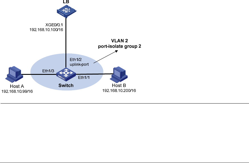
As shown in Figure 35, Host A and Host B belong to the same VLAN, and connect to Switch via Ethernet
1/3 and Ethernet 1/1 respectively. Switch connects to LB module via Ethernet 1/2.
Configure port isolation on Ethernet 1/3 and Ethernet 1/1 of Switch. Enable proxy ARP on LB module
to allow communication between Host A and Host B at Layer 3.
Figure 35 Network diagram for local proxy ARP between isolated ports
NOTE:
• The switch in this diagram is a distributed device.
• In this configuration example, all traffic between the hosts is blocked, so you need to configure local
proxy ARP on Ten-GigabitEthernet 0/0.1 of LB module to enable communication between Host A and
Host B. If the two ports (Ethernet 1/3 and Ethernet 1/1) on the switch are isolated only at Layer 2, you
can enable communication between the two hosts by configuring local proxy ARP on VLAN-interface 2
of the switch.