
R3204P16-HP Load Balancing Module Network Management Configuration Guide-6PW101

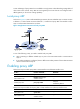
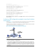
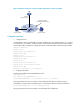
Table Of Contents
- Title page
- Contents
- Interface management configuration
- IP addressing configuration
- MAC address table configuration
- Layer 2 forwarding configuration
- Layer 2 forwarding overview
- Configuring general Layer 2 forwarding
- Configuring inline Layer 2 forwarding
- Configuring inter-VLAN Layer 2 forwarding
- Forward-type inline Layer 2 forwarding configuration example
- Blackhole-type inline Layer 2 forwarding configuration example
- Inter-VLAN Layer 2 forwarding configuration example
- VLAN configuration
- ARP configuration
- Gratuitous ARP configuration
- Proxy ARP configuration
- Layer 3 forwarding configuration
- NAT configuration
- Overview
- Configuring a NAT policy in the web interface
- Configuring NAT in the CLIs
- Configuration guidelines
- ALG configuration
- Static route configuration
- RIP configuration
- OSPF configuration
- BGP configuration
- Policy-based routing configuration
- Route displaying
- DNS configuration
- Overview
- Configuring DNS on the web interface
- Configuring DNS in the CLIs
- Troubleshooting IPv4 DNS configuration
- Support and other resources
- Index
70
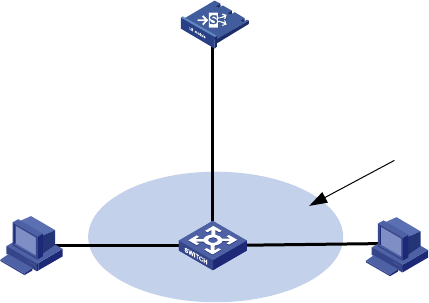
Figure 36 Network diagram for local proxy ARP configuration in isolate-user-VLAN
Configuration procedure
1. Configure Switch
# Create VLAN 2, VLAN 3, and VLAN 5 on Switch. Add Ethernet 1/3 to VLAN 2, Ethernet 1/1 to VLAN
3, and Ethernet 1/2 to VLAN 5. Configure VLAN 5 as the isolate-user-VLAN, and VLAN 2 and VLAN 3
as secondary VLANs. Configure the mappings between isolate-user-VLAN and the secondary VLANs.
<Switch> system-view
[Switch] vlan 2
[Switch-vlan2] port ethernet 1/3
[Switch-vlan2] quit
[Switch] vlan 3
[Switch-vlan3] port ethernet 1/1
[Switch-vlan3] quit
[Switch] vlan 5
[Switch-vlan5] port ethernet 1/2
[Switch-vlan5] isolate-user-vlan enable
[Switch-vlan5] quit
[Switch] isolate-user-vlan 5 secondary 2 3
2. Configure LB module
# Specify the IP address of Ten-GigabitEthernet 0/0.1.
<LB> system-view
[LB] interface Ten-GigabitEthernet 0/0.1
[LB-Ten-GigabitEthernet0/0.1] ip address 192.168.10.100 255.255.0.0
The ping operation from Host A to Host B is unsuccessful because they are isolated at Layer 2.
# Configure local proxy ARP to implement Layer 3 communication between VLAN 2 and VLAN 3.
[LB-Ten-GigabitEthernet0/0.1] local-proxy-arp enable
The ping operation from Host A to Host B is successful after the configuration.
LB
Switch
Eth1/3
VLAN 2
Eth1/1
VLAN 3
Eth1/2
VLAN 5
Host A
192.168.10.99/16
Host B
192.168.10.200/16
Isolate-user-vlan 5
Secondary VLAN 2 and 3
XGE0/0.1
192.168.10.100/16