
R3204P16-HP Load Balancing Module Network Management Configuration Guide-6PW101


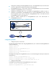

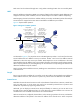
Table Of Contents
- Title page
- Contents
- Interface management configuration
- IP addressing configuration
- MAC address table configuration
- Layer 2 forwarding configuration
- Layer 2 forwarding overview
- Configuring general Layer 2 forwarding
- Configuring inline Layer 2 forwarding
- Configuring inter-VLAN Layer 2 forwarding
- Forward-type inline Layer 2 forwarding configuration example
- Blackhole-type inline Layer 2 forwarding configuration example
- Inter-VLAN Layer 2 forwarding configuration example
- VLAN configuration
- ARP configuration
- Gratuitous ARP configuration
- Proxy ARP configuration
- Layer 3 forwarding configuration
- NAT configuration
- Overview
- Configuring a NAT policy in the web interface
- Configuring NAT in the CLIs
- Configuration guidelines
- ALG configuration
- Static route configuration
- RIP configuration
- OSPF configuration
- BGP configuration
- Policy-based routing configuration
- Route displaying
- DNS configuration
- Overview
- Configuring DNS on the web interface
- Configuring DNS in the CLIs
- Troubleshooting IPv4 DNS configuration
- Support and other resources
- Index
82
NAT control can be achieved through ACLs. Only packets matching the ACL rules are served by NAT.
NAPT
Network Address Port Translation (NAPT) is a variation of NAT. It allows multiple internal addresses to be
mapped to the same public IP address, which is called multiple-to-one NAT or address multiplexing.
NAPT mapping is based on both the IP address and the port number. With NAPT, packets from multiple
internal hosts are mapped to the same external IP address with different port numbers.
Figure 41 dep
icts NAPT operation.
Figure 41 Diagram for NAPT operation
As illustrated in Figure 41, four IP packets arrive at the NAT gateway. Packets 1 and 2 are from the same
internal address but have different source port numbers. Packets 3 and 4 are from different internal
addresses but have the same source port number. NAPT maps their source IP addresses to the same
external address but with different source port numbers. Therefore, the packets can still be discriminated.
When response packets arrive, the NAT gateway can forward them to corresponding hosts based on the
destination addresses and port numbers.
NAPT can better utilize IP address resources, enabling more internal hosts to access the external network
at the same time.
Easy IP
Easy IP uses the public IP address of an interface on the LB module as the translated source address to
save IP address resources, and uses ACLs to permit only certain internal IP addresses to be NATed.
Internal server
NAT hides the internal network structure as well as the identities of internal hosts. However, internal hosts
such as a Web server or an FTP server may need to be accessed by external hosts in practice. NAT
satisfies this requirement by supporting internal servers.
With NAT, you can deploy an internal server easily and flexibly. For instance, you can use 20.1.1.10 as
the Web server’s external address and 20.1.1.11 as the FTP server’s external address. You can even use
an address like 20.1.1.12:8080 as the Web server’s external address.
With an internal server configured, the NAT device, when receiving a packet to the server, translates the
destination address of the packet to the internal IP address of the internal server. When a response
192.168.1.3
Internet
IP packet 2
Source IP : 192.168.1.3
Source port : 2468
IP packet 2
Source IP : 20.1.1.1
Source port : 2002
192.168.1.1 20.1.1.1
IP packet 3
Source IP : 20.1.1.1
Source port : 2003
IP packet 3
Source IP : 192.168.1.1
Source port : 1111
1.1.1.2
1.1.1.3
Server B
Host
Server A
192.168.1.2
Host
IP packet 1
Source IP : 192.168.1.3
Source port : 1537
IP packet 1
Source IP : 20.1.1.1
Source port : 2001
IP packet 4
Source IP : 20.1.1.1
Source port : 2004
IP packet 4
Source IP : 192.168.1.2
Source port : 1111