
R3204P16-HP Load Balancing Module Network Management Configuration Guide-6PW101
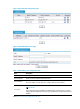
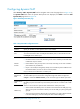
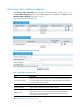
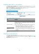
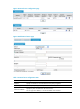
Table Of Contents
- Title page
- Contents
- Interface management configuration
- IP addressing configuration
- MAC address table configuration
- Layer 2 forwarding configuration
- Layer 2 forwarding overview
- Configuring general Layer 2 forwarding
- Configuring inline Layer 2 forwarding
- Configuring inter-VLAN Layer 2 forwarding
- Forward-type inline Layer 2 forwarding configuration example
- Blackhole-type inline Layer 2 forwarding configuration example
- Inter-VLAN Layer 2 forwarding configuration example
- VLAN configuration
- ARP configuration
- Gratuitous ARP configuration
- Proxy ARP configuration
- Layer 3 forwarding configuration
- NAT configuration
- Overview
- Configuring a NAT policy in the web interface
- Configuring NAT in the CLIs
- Configuration guidelines
- ALG configuration
- Static route configuration
- RIP configuration
- OSPF configuration
- BGP configuration
- Policy-based routing configuration
- Route displaying
- DNS configuration
- Overview
- Configuring DNS on the web interface
- Configuring DNS in the CLIs
- Troubleshooting IPv4 DNS configuration
- Support and other resources
- Index
84
device if one device fails. However, if the devices select the same IP addresses from their address pool
and assign them the same port numbers, reverse sessions on the two devices are the same. As a result,
session data cannot be backed up between the devices.
To solve the problem, the low-priority address pool attribute is introduced to NAT. You can configure
address pools on the two devices to have different priorities. For example, suppose that two addresses
pools, 100.0.0.1 through 100.0.0.5 (A), and 100.0.0.6 through 100.0.0.10 (B), are configured on the
two devices. You can configure A as the low-priority address pool on a device and configure B as the
low-priority address pool on the other device. Because addresses in the low-priority address pool are not
selected by NAT. The two devices use different addresses as translated source addresses, and thus
session data can be backed up successfully.
NOTE:
For more information about stateful failover, see
High Availability Configuration Guide
.
Configuring a NAT policy in the web interface
Configuration overview
Configuring address translation
A NAT gateway can be configured with or dynamically generate mapping entries to translate between
internal and external network addresses. Generally, address translation can be classified into two types,
dynamic and static.
• Dynamic NAT
A dynamic NAT entry is generated dynamically. Dynamic NAT is implemented by associating an ACL
with an address pool (or the address of an interface in the case of Easy IP). This association defines what
packets can use the addresses in the address pool (or the interface’s address) to access the external
network. Dynamic NAT is applicable when a large number of internal users need to access external
networks. An IP address is selected from the associated address pool to translate an outgoing packet.
After the session terminates, the selected IP address is released.
Perform the tasks in Table 10 t
o configure dynamic NAT.
Table 10 Dynamic NAT configuration task list
Task Remarks
Creating an address pool Required for configuring NAPT and many-to-many NAT
Configuring dynamic NAT
Required
Configure dynamic NAT on an interface.
• Static NAT
The mapping relationships between external and internal network addresses are manually configured.
Static NAT can meet fixed access requirements of a few users.
Perform the tasks in Table 11 to c
onfigure static NAT.