HP Load Balancing Module Security Configuration Guide Part number: 5998-2686 Document version: 6PW101-20120217
Legal and notice information © Copyright 2012 Hewlett-Packard Development Company, L.P. No part of this documentation may be reproduced or transmitted in any form or by any means without prior written consent of Hewlett-Packard Development Company, L.P. The information contained herein is subject to change without notice.
Contents Zone configuration ······················································································································································· 1 Configuring a zone ··························································································································································· 2 Configuration task list ·································································································································
Enabling TCP proxy for a security zone ············································································································· 41 Adding a protected IP address entry··················································································································· 42 Displaying information about protected IP address entries ·············································································· 42 TCP proxy configuration example ··································
Configuring an entity DN ····································································································································· 89 Configuring a PKI domain ···································································································································· 91 Submitting a PKI certificate request ····················································································································· 92 Submitting a certificate reques
AAA configuration task list ································································································································· 134 RADIUS configuration task list···························································································································· 134 Configuring AAA ························································································································································· 135 Configuration pre
Connection limit configuration ······························································································································· 174 Connection limit overview ··········································································································································· 174 Connection limit configuration task list ······················································································································ 174 Creating a conn
Index ········································································································································································ 198 vi
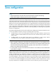
Zone configuration NOTE: • The term firewall in this document refers to network devices that support load balancing. • The LB module supports configuring zones only in the web interface. Traditional firewall/router policies are configured based on packet inbound and outbound interfaces on early dual-homed firewalls. With the development of firewalls, they can not only connect the internal and external network, but also connect the internal network, external network, and the Demilitarized Zone (DMZ).
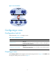
Figure 1 Zone classification Configuring a zone Configuration task list Perform the tasks in Table 1 to configure a zone. Table 1 Zone configuration task list Task Remarks Optional Creating a zone By default, the following zones are available on the device: Management, Local, Trust, DMZ and Untrust. Required Configuring a zone member Add specified subnet address source, interfaces, Layer 2 Ethernet interface + VLAN to the created zone.
Figure 2 Zone Figure 3 Create a zone Table 2 Configuration items for creating a zone Item Description Zone ID Set the zone ID. Zone Name Set the zone name. Preference Set the preference of a zone. By default, packets from a high priority zone to a low priority zone are allowed to pass. Return to Zone configuration task list. Configuring a zone member Select Security > Zone from the navigation tree to enter the page as shown in Figure 2.
Figure 4 Modify zone Table 3 Configuration items for modifying a zone Item Description Zone ID Displays the zone ID. Zone Name Displays the zone name. Set the preference of the specified zone Preference By default, packets from a high priority zone to a low priority zone are allowed to pass. Set the interfaces to be added to the zone.
• The internal network is a trust network and can access the server and the external network. You can deploy the internal network in the Trust zone with a higher priority and connect interface Ten-GigabitEthernet 0/0.1 on the LB card to the external network. • The external network is an untrusted network, and you need to use strict security rules to control access from the external network to the internal network and the server.
Figure 6 Configure the Trust zone • Select the Ten-GigabitEthernet0/0.1 option. • Click Apply. # Configure the DMZ zone, and add interface Ten-GigabitEthernet 0/0.3 to the DMZ zone. • Click Back to return to the page for displaying zones to perform the following configurations, as shown in Figure 7.
Figure 7 Configure the DMZ zone • Click the icon of the DMZ zone. • Select the Ten-GigabitEthernet0/0.3 option. • Click Apply. # Configure the Untrust zone and add interface Ten-GigabitEthernet 0/0.2 to the Untrust zone. • Click Back to return to the page for displaying zones. • Click the 8.
Figure 8 Configure the Untrust zone • Select the Ten-GigabitEthernet0/0.2 option. • Click Apply.
Virtual fragment reassembly NOTE: The LB modules support virtual fragment reassembly in the web interface only. Virtual fragment reassembly overview To prevent service modules (such as NAT) from processing packet fragments that arrive out of order, you can enable the virtual fragment reassembly feature. This feature can virtually reassemble the fragments of a datagram through fragment checking, sequencing and caching so as to ensure that fragments arrive at service modules in order.
Table 4 Virtual fragment reassembly configuration items Item Description Security Zone Specify a security zone to be configured with virtual fragment reassembly. Enable Virtual Fragment Reassembly Select the check box to enable the virtual fragment reassembly feature. Specify max number of concurrent reassemblies Specify the maximum number of concurrent reassemblies. When this value is reached, the LB module discards all subsequent packets and sends a syslog message.
• Select Security > NAT from the navigation tree, and in the right pane select the Static NAT tab. Then click Add in the Static Address Mapping area to enter the page shown in Figure 11. Figure 11 Add a static address mapping • Type 1.1.1.1 for Internal IP Address. • Type 2.2.2.3 for Global IP Address. • Click Apply. # Enable static NAT on Ten-GigabitEthernet 0/0.2. • In the Interface Static Translation area of the Static NAT tab, click Add to enter the page shown in Figure 12.
Figure 13 Configure virtual reassembly • Select Trust for Security Zone. • Select Enable Virtual Fragment Reassembly. • Click Apply. After the configuration, if receiving disordered fragments from security zone Trust, the LB module will check and reassemble them. Configuration guidelines • The virtual fragment reassembly feature only applies to packets incoming to a security zone. • The virtual fragment reassembly feature does not support load sharing.
Blacklist configuration NOTE: The LB module supports configuring the blacklist function only in the web interface. Overview Blacklist is an attack prevention mechanism that filters packets based on source IP address. Compared with ACL-based packet filtering, the blacklist feature is easier to configure and fast in filtering packets sourced from particular IP addresses. The LB module can dynamically add and remove blacklist entries. This is implemented in cooperation with the scanning detection feature.
Task Remarks Viewing the blacklist Optional Enabling the blacklist function Select Security > Intrusion Detection from the navigation tree and then select the Blacklist tab to enter the blacklist management page, as shown in Figure 14. Then, select the Enable Blacklist option and click Apply to enable the blacklist feature. Figure 14 Blacklist management page Return to Blacklist configuration task list.
Return to Blacklist configuration task list. Viewing the blacklist Select Security > Intrusion Detection from the navigation tree and then select the Blacklist tab to enter the blacklist management page, where you can view the blacklist information, as shown in Figure 14. Table 7 describes the blacklist fields. Table 7 Blacklist fields Item Description IP Address Blacklisted IP address Type of the blacklist entry, which can be: • Auto: Added by the scanning detection feature automatically.
Configuration procedure # Assign IP addresses to the interfaces. (Omitted) # Enable the blacklist feature. Select Security > Intrusion Detection from the navigation tree and then select the Blacklist tab to enter the blacklist management page. Perform configuration as shown in Figure 17. Figure 17 Enable the blacklist feature • In the Global Configuration area, select the Enable Blacklist option. • Click Apply. # Add a blacklist entry for Host D.
Figure 19 Add a blacklist entry for Host C • Enter IP address 192.168.1.5. • Select the Hold Time option and, in the box next to the option, set the lifetime of the entry to 50 minutes. • Click Apply to complete the configuration. # Configure scanning detection for the untrusted zone. Select Security > Intrusion Detection from the navigation tree and then select the Scanning Detection tab. Perform the configurations shown in Figure 20.
Packet inspection configuration NOTE: The LB module supports configuring packet inspection only in the web interface. Overview A single-packet attack is also called a malformed packet attack. A single-packet attack occurs when: • An attacker sends defective IP packets, such as overlapping IP fragments and packets with illegal TCP flags, to a target system, making the target system malfunction or crash when processing such packets.
Attack type Description Tracert The Tracert program usually sends UDP packets with a large destination port number and an increasing TTL (starting from 1). The TTL of a packet is decreased by 1 when the packet passes each router. Upon receiving a packet with a TTL of 0, a router must send an ICMP time exceeded message back to the source IP address of the packet. A Tracert attacker exploits the Tracert program to figure out the network topology.
Item Description Enable Fraggle Attack Detection Enable or disable detection of Fraggle attacks. Enable Land Attack Detection Enable or disable detection of Land attacks. Enable WinNuke Attack Detection Enable or disable detection of WinNuke attacks. Enable TCP Flag Attack Detection Enable or disable detection of TCP flag attacks. Enable ICMP Unreachable Packet Attack Detection Enable or disable detection of ICMP unreachable attacks.
Figure 23 Enable Land and Smurf attack detection for the untrusted zone 1. Select Untrust from the Zone dropdown list. 2. Select Discard Packets when the specified attack is detected. 3. Select Enable Land Attack Detection. 4. Select Enable Smurf Attack Detection. 5. Click Apply to complete the configuration. Configuration verification Check that the module can detect Land and Smurf attacks from the untrusted zone, output alarm logs accordingly, and drop the attack packets.
Traffic abnormality detection configuration NOTE: The LB module supports configuring traffic abnormality detection only in the web interface. Overview The traffic abnormality detection feature analyzes the characteristics of traffic to detect abnormal traffic and take countermeasures accordingly. Supported countermeasures include outputting alarm logs, dropping packets, and blacklisting the source of the packets.
Connection limit When an internal user initiates a large number of connections to a host on the external network in a short period of time, system resources on the module will be used up soon. This will make the module unable to service other users. In addition, if an internal server receives large quantities of connection requests in a short period of time, the server will not be able to process normal connection requests from other hosts.
Figure 24 ICMP flood detection configuration page Do the following to configure ICMP flood detection: 1. In the Attack Prevention Policy area, specify the protection action to be taken upon detection of an ICMP flood attack. If you do not select the Discard packets when the specified attack is detected option, the module only collects ICMP flood attack statistics. 2.
NOTE: • In a security zone, you can configure multiple protected hosts and one global connection rate threshold. • For a host, the host-specific setting overrides the global setting of the security zone in case conflict occurs. Configuring UDP flood detection NOTE: UDP flood detection is mainly intended to protect servers and is usually configured for an internal zone.
Figure 27 Add a UDP flood detection rule Table 11 describes the configuration items. Table 11 UDP flood detection configuration items Item Protected Host Configuration Global Configuration of Security Zone Description IP Address Specify the IP address of the protected host. Connection Rate Threshold Set the maximum UDP connection rate for the IP address. Connection Rate Threshold Set the global maximum UDP connection rate for each host in the current security zone.
Figure 28 SYN flood detection configuration page Do the following to configure SYN flood detection: 1. In the Attack Prevention Policy area, specify the protection actions to be taken upon detection of a SYN flood attack. If you do not select any option, the module only collects SYN flood attack statistics. The available protection actions include: a. Discard packets when the specified attack is detected.
Figure 29 Add a SYN flood detection rule Table 12 describes the configuration items. Table 12 SYN flood detection configuration items Item Protected Host Configuration Global Configuration of Security Zone Description IP Address Specify the IP address of the protected host. Connection Rate Threshold Set the maximum TCP connection rate for the IP address. Half Connection Count Set the maximum number of the half-open TCP connections that can be present for the IP address.
Figure 30 Connection limit configuration page Table 13 describes the connection limit configuration items. Table 13 Connection limit configuration items Item Description Security Zone Select a security zone to perform connection limit configuration for it. Discard packets when the specified attack is detected Select this option to discard subsequent packets destined for or sourced from an IP address when the number of the connections for that IP address has exceeded the limit.
Table 14 Scanning detection configuration items Item Description Security Zone Select a security zone to perform scanning detection configuration for it. Enable Scanning Detection Select this option to enable scanning detection for the security zone. Scanning Threshold Set the maximum connection rate for a source IP address. Select this option to allow the system to blacklist a suspicious source IP address.
Figure 32 Network diagram for traffic abnormality detection configuration Configuration procedure # Assign IP addresses to interfaces. (Omitted) # Enable the blacklist feature. Select Security > Intrusion Detection from the navigation tree and then select the Blacklist tab and perform the configuration shown in Figure 33. Figure 33 Enable the blacklist feature • In the Global Configuration area, select the Enable Blacklist option. • Click Apply. # Configure scanning detection for the untrusted zone.
• Select zone Untrust. • Select the Enable Scanning Detection option. • Set the scanning threshold to 4500 connections per second. • Select the Add the source IP to the blacklist option. • Click Apply. # Configure connection limit for the trusted zone. Select Security > Intrusion Detection from the navigation tree and then select the Connection Limit tab to enter the connection limit configuration page and perform the configurations shown in Figure 35.
Figure 37 Configure SYN flood detection for the DMZ • Select zone DMZ. • In the Attack Prevention Policy area, select the Discard packets when the specified attack is detected option. • Click Apply. • In the SYN Flood Configuration area, click Add. • On the page that appears, perform the configurations shown in Figure 38. Figure 38 Specify the objects to be protected in the DMZ • Select the Protected Host Configuration option. • Specify the IP address as 10.1.1.2.
• After a scanning attack packet is received from zone Untrust, the module should output alarm logs and add the IP address of the attacker to the blacklist. You can select Security > Intrusion Detection from the navigation tree and then select the Blacklist tab to view whether the attacker’s IP address is on the blacklist. • If a host in zone Trust initiates 100 or more connections, the module should output alarm logs and discard subsequent connection request packets from the host.
Intrusion detection statistics NOTE: The LB module supports configuring intrusion detection only in the web interface. Overview Intrusion detection is an important network security feature. By analyzing the contents and behaviors of packets passing by, it can determine whether the packets are attack packets and take actions accordingly as configured. Supported actions include outputting alarm logs, discarding packets, and adding the attacker to the blacklist.
Table 15 describes the attack types. Table 15 Description of attack types Attack type Description Fraggle A Fraggle attack occurs when an attacker sends large amounts of UDP echo requests with the UDP port number being 7 or Chargen packets with the UDP port number being 19, resulting in a large quantity of junk replies and finally exhausting the bandwidth of the target network.
Attack type Description SYN Flood A SYN flood attack exploits TCP SYN packets. Due to resource limitation, the number of TCP connections that can be created on a device is limited. A SYN flood attacker sends a barrage of spurious SYN packets to a victim to initiate TCP connections.
TCP proxy configuration NOTE: The LB module supports configuring TCP proxy only in the web interface. Overview Introduction to SYN flood attack As a general rule, the establishment of a TCP connection is a three-way handshake: 1. The request originator sends a SYN message to the target server. 2. After receiving the SYN message, the target server establishes a TCP connection in the SYN_RECEIVED state, returns a SYN ACK message to the originator, and waits for a response. 3.
Figure 40 Network diagram for unidirectional proxy As shown in Figure 41, all packets between the TCP client and TCP server go through the TCP proxy, and thus you can configure unidirectional proxy or bidirectional proxy as desired. Figure 41 Network diagram for unidirectional/bidirectional proxy How TCP proxy works Unidirectional proxy Figure 42 shows the data exchange process of unidirectional proxy.
After the TCP connection is established, the TCP proxy forwards the subsequent packets of the connection without additional processing. Bidirectional proxy Figure 43 shows the data exchange process of bidirectional proxy. Figure 43 Data exchange process of bidirectional proxy After receiving a SYN message from a client to the protected server (such a message matches a protected IP address entry), the TCP proxy sends back a SYN ACK message with the window size being 0 on behalf of the server.
Task Remarks At least one method is required. Adding a protected IP address entry You can add protected IP address entries by either of the methods: • Static: Add entries manually. By default, no such entries are configured in the system. • Dynamic: Select Security > Intrusion Detection from the navigation tree and then select the SYN Flood tab. Select the Add protected IP entry to TCP Proxy check box.
• The icon indicates that the TCP proxy feature is enabled for the corresponding security zone. You can click the Disable button beside the icon to disable the feature. Return to TCP proxy configuration task list. Adding a protected IP address entry Select Security > Intrusion Detection from the navigation tree and then select the Protected IP Configuration tab to enter the page that lists information about protected IP address entries and the relative statistics, as shown in Figure 45.
Table 19 Information about protected IP address entries Item Description Protected IP IP addresses protected by the TCP proxy feature. Destination port of the TCP connection. Port Number The option any specifies that TCP proxy services TCP connection requests to any port of the server at the destination IP address. Type The protected IP address entries can be static or dynamic. Lifetime(min) Lifetime for the IP address entry under protection.
Figure 48 Select the bidirectional mode and enable TCP proxy for zone Untrust • Select Bidirection for the global setting. • Click Apply. • In the Zone Configuration area, click Enable for the Untrust zone. # Add an IP address entry manually for protection. • Select the Protected IP Configuration tab. Then on the right pane, click Add. Add an IP address entry for protection as shown in Figure 49. Figure 49 Add an IP address entry for protection • Type 20.0.0.
• Select Trust from the Security Zone drop-down list. • Select the Add protected IP entry to TCP Proxy check box in the Attack Prevention Policy area. • Click Apply. • In the SYN Flood Configuration area, click Add. Configure global settings as shown in Figure 51. Figure 51 Configure global settings • Select Global Configuration of Security Zone. • Use the default values for the connection rate threshold and half connection count threshold. • Click Apply.
ACL configuration NOTE: ACLs refer to IPv4 ACLs throughout this document. ACL overview An access control list (ACL) is a set of rules (or permit or deny statements) for identifying traffic based on criteria such as source IP address, destination IP address, and port number. ACLs are primarily used for packet filtering. You can use ACLs in firewall, routing, and other feature modules for identifying traffic. The packet drop or forwarding decisions varies with the modules that use ACLs.
• auto—Sorts ACL rules in depth-first order. Depth-first ordering ensures that any subset of a rule is always matched before the rule. Table 20 lists the sequence of tie breakers that depth-first ordering uses to sort rules for each type of ACL. Table 20 Sort ACL rules in depth-first order ACL category Sequence of tie breakers 1. More 0s in the source IP address wildcard (more 0s means a narrower IP address range) 2. Smaller rule ID 1.
Automatic rule numbering and renumbering The ID automatically assigned to an ACL rule takes the nearest higher multiple of the numbering step to the current highest rule ID, starting with 0. For example, if the numbering step is 5 (the default), and there are five ACL rules numbered 0, 5, 9, 10, and 12, the newly defined rule is numbered 15. If the ACL does not contain any rule, the first rule is numbered 0. Whenever the step changes, the rules are renumbered, starting from 0.
Task Remarks Configuring a basic ACL rule Required Configuring an advance ACL rule Complete one of the three tasks according to the ACL category. IMPORTANT: Configuring an Ethernet frame header ACL rule • Within an ACL, the permit or deny statement of each rule must be unique. If the ACL rule you are creating or editing has the same deny or permit statement as another rule in the ACL, your creation or editing attempt will fail. • You can edit ACL rules only when the match order is config.
Figure 53 Time range configuration page Table 22 Time range configuration items Item Description Name Type the name for the time range. Periodic Time Range Absolute Time Range Start Time Set the start time of the periodic time range, in the hh:mm format (24-hour clock). End Time Set the end time of the periodic time range, in the hh:mm format (24-hour clock). The end time must be greater than the start time. Sun., Mon., Tues., Wed., Thurs., Fri., and Sat.
Figure 55 ACL configuration page Table 23 describes the configuration items for creating an ACL. Table 23 ACL configuration items Item ACL Number Description Type a number for the ACL. The value ranges of the ACL number vary by device. Select a match order for the ACL. Available values are: Match Order • Config: Sorts ACL rules in ascending order of rule ID. • Auto: Sorts ACL rules in depth-first order. Return to ACL configuration task list.
Figure 57 Basic ACL rule configuration page Table 24 Basic ACL rule configuration items Item Description Select the Rule ID check box and type a number for the rule. Rule ID If you do not specify a rule number, the system automatically assigns one for the rule. IMPORTANT: If the rule already exists, the configuration overwrites the old rule. Select the operation to be performed for packets matching the rule. Operation • Permit: Allows matching packets to pass. • Deny: Denies matching packets.
of the ACL, as shown in Figure 58. Click Add to enter the advanced ACL rule configuration page, as shown in Figure 59. Figure 58 List of advanced ACL rules Figure 59 Advanced ACL rule configuration page Table 25 Advanced ACL rule configuration items Item Description Select the Rule ID check box and type a number for the rule. Rule ID If you do not specify the rule number, the system assigns one automatically. IMPORTANT: If the rule already exists, the configuration overwrites the old rule.
Item Description Select a time range for the rule. If you select None, the rule will always be effective. Time Range Available time ranges are configured by selecting Security > Time Range from the navigation tree. Non-first Fragments Only Select this check box to apply the rule to only non-first fragments. If you do no select this check box, the rule applies to all fragments and non-fragments. Select this check box to log matching IPv4 packets.
Item Description ToS Specify the ToS preference. Precedence Specify the IP precedence. DSCP Specify the DSCP priority. IMPORTANT: If you configure the IP precedence or ToS precedence in addition to the DSCP priority, the DSCP priority takes effect. Return to ACL configuration task list. Configuring an Ethernet frame header ACL rule Select Security > ACL from the navigation tree.
Item Description Select the operation to be performed for packets matching the rule. Operation • Permit: Allows matching packets to pass. • Deny: Denies matching packets. Select a time range for the rule. Time Range Source MAC Address Source Wildcard Destination MAC Address Destination Wildcard If you select None, the rule will always be effective. Available time ranges are configured by selecting Security > Time Range from the navigation tree.
Figure 62 Network diagram for ACL configuration Configuration procedure # Configure an IPv4 advanced ACL. • Select Security > ACL from the navigation tree, and then click Add. • Type the ACL number 3000. • Select the match order Config. • Click Apply. Figure 63 Configure an IPv4 advanced ACL # Configure a rule to deny packets sourced from hosts in the Marketing department. • From the ACL list, select ACL 3000 and click the icon in the Operation column.
Figure 64 Configure a rule to deny packets sourced from hosts in the Marketing department # Configure a rule to deny packets sourced from hosts in the R&D department. • On the page displaying the rules of ACL 3000, click Add. Figure 65 Advanced ACL 3000 rule list • Click the Rule ID check box, and type 1 in the text box. • Select Deny as the operation. • Select Source IP Address check box and type 192.168.2.0 and 0.0.0.255 in the following text boxes.
Figure 66 Configure a rule to deny packets sourced from hosts in the R&D department # Configure a rule to allow packets sourced from hosts in the Accounting department to the salary server. • On the page displaying rules of ACL 3000, click Add. Figure 67 Advanced ACL 3000 rule list • Click the Rule ID check box, and type 2 in the text box. • Select Permit as the operation. • Select Source IP Address check box, and type 192.168.3.0 and 0.0.0.255 in the following text boxes.
Figure 68 Configure a rule to allow hosts in the Accounting department to access the salary server Configuring an ACL at the CLI ACL configuration task list Complete the following tasks to configure an ACL: Task Remarks Configuring a time range Optional Configuring an IPv4 basic ACL Required Configuring an IPv4 advanced ACL Configure at least one task. IMPORTANT: • Within an ACL, the permit or deny statement of each rule Configuring an Ethernet frame header ACL must be unique.
Configuring an ACL Configuring a time range You can implement ACL rules based on the time of day by applying a time range to them. A time-based ACL rule takes effect only in any time periods specified by the time range. The following basic types of time range are available: • Periodic time range—Recurs periodically on a day or days of the week. • Absolute time range—Represents only a period of time and does not recur. You can create multiple statements in a time range.
To do… Use the command… Set the rule numbering step step step-value Create or edit a rule rule [ rule-id ] { deny | permit } [ counting | fragment | logging | source { sour-addr sour-wildcard | any } | time-range time-range-name ] * Remarks Optional 5 by default. Required By default, an IPv4 basic ACL does not contain any rule. Optional Add or edit a rule comment rule rule-id comment text By default, an IPv4 ACL rule has no rule description.
To do… Use the command… Create or edit a rule rule [ rule-id ] { deny | permit } protocol [ { { ack ack-value | fin fin-value | psh psh-value | rst rst-value | syn syn-value | urg urg-value } * | established } | counting | destination { dest-addr dest-wildcard | any } | destination-port operator port1 [ port2 ] | dscp dscp | fragment | icmp-type { icmp-type [ icmp-code ] | icmp-message } | logging | precedence precedence | reflective | source { sour-addr sour-wildcard | any } | source-port operator port1
To do… Add or edit a rule comment Use the command… Remarks Optional rule rule-id comment text By default, an Ethernet frame header ACL rule has no rule description. Copying an IPv4 ACL You can create an ACL by copying an existing ACL (source ACL). The new ACL (destination ACL) has the same properties and content as the source ACL, but not the same ACL number and name. To successfully copy an ACL, make sure that: • The destination ACL number is from the same category as the source ACL number.
To do... Use the command… Remarks Display the configuration and status of one or all time ranges display time-range { time-range-name | all } Available in any view Clear statistics for one or all IPv4 ACLs reset acl counter { acl-number | all | name acl-name } Available in user view ACL configuration examples Network requirements A company interconnects its departments through a LB module. Configure an ACL to: • Permit access from the President's office at any time to the salary database server.
[LB-acl-adv-3000] rule 2 deny ip source any destination 129.110.1.2 0.0.0.0 time-range trname [LB-acl-adv-3000] quit 3. Apply the ACL # Enable IPv4 firewall, and apply IPv4 ACL 3000 to filter outgoing packets on interface Ten-GigabitEthernet 0/0.4. [LB] firewall enable [LB] interface Ten-GigabitEthernet 0/0.4 [LB-Ten-GigabitEthernet0/0.
PKI configuration PKI overview Introduction to PKI The Public Key Infrastructure (PKI) is a general security infrastructure for providing information security through public key technologies. PKI, also called asymmetric key infrastructure, uses a key pair to encrypt and decrypt the data. The key pair consists of a private key and a public key. The private key must be kept secret while the public key needs to be distributed. Data encrypted by one of the two keys can only be decrypted by the other.
CA policy A CA policy is a set of criteria that a CA follows in processing certificate requests, issuing and revoking certificates, and publishing CRLs. Usually, a CA advertises its policy in the form of certification practice statement (CPS). A CA policy can be acquired through out-of-band means such as phone, disk, and e-mail.
LDAP is a protocol for accessing and managing PKI information. An LDAP server stores user information and digital certificates from the RA server and provides directory navigation service. From an LDAP server, an entity can retrieve digital certificates of its own and other entities. Applications of PKI The PKI technology can satisfy the security requirements of online transactions. As an infrastructure, PKI has a wide range of applications. Here are some application examples.
• Auto—In auto mode, an entity automatically requests a certificate through Simple Certification Enrollment Protocol (SCEP, a dedicated protocol for an entity to communicate with a CA) when it has no local certificate or the present certificate is about to expire. You can specify the PKI certificate request mode for a PKI domain.
Task Remarks Required When requesting a certificate, an entity introduces itself to the CA by providing its identity information and public key, which will be the major components of the certificate. A certificate request can be submitted to a CA in two ways: online and offline. Requesting a local certificate • In online mode, if the request is granted, the local certificate will be retrieved to the local system automatically.
Task Remarks Optional Destroying the RSA key pair Destroy the existing RSA key pair and the corresponding local certificate. If the certificate to be retrieved contains an RSA key pair, you need to destroy the existing RSA key pair. Otherwise, the retrieving operation will fail. Optional Retrieve an existing certificate and display its information. TIP: Retrieving and displaying a certificate • Before retrieving a local certificate in online mode, be sure to complete LDAP server configuration.
Table 29 PKI entity configuration items Item Description Entity Name Type the name for the PKI entity. Common Name Type the common name for the entity. IP Address Type the IP address of the entity. Type the fully qualified domain name (FQDN) for the entity. FQDN An FQDN is a unique identifier of an entity on the network. It consists of a host name and a domain name and can be resolved to an IP address. For example, www.whatever.com is an FQDN, where www indicates the host name and whatever.
Figure 74 PKI domain configuration page Table 30 PKI domain configuration items Item Description Domain Name Type the name for the PKI domain. Type the identifier of the trusted CA. An entity requests a certificate from a trusted CA. The trusted CA takes the responsibility of certificate registration, distribution, and revocation, and query. CA Identifier TIP: • In offline mode, this item is optional; while in other modes, this item is required.
Item Description Type the URL of the RA. The entity will submit the certificate request to the server at this URL through the SCEP protocol. The SCEP protocol is intended for communication between an entity and an authentication authority. Requesting URL In offline mode, this item is optional; while in other modes, this item is required. TIP: • In offline mode, this item is optional; while in other modes, this item is required. • This item does not support domain name resolution.
Item Description Type the URL of the CRL distribution point. This item is available when the Enable CRL Checking check box is selected. CRL URL Note that when the URL of the CRL distribution point is not set, you should acquire the CA certificate and a local certificate, and then acquire a CRL through SCEP. TIP: This item does not support domain name resolution. Return to Configuration task list for requesting a certificate manually.
Destroying the RSA key pair Select Security > PKI > Certificate from the navigation tree to display existing PKI certificates, as shown in Figure 75. Click Destroy Key to enter the RSA key pair destruction page, as shown in Figure 77. Then, click Apply to destroy the existing RSA key pair and the corresponding local certificate. Figure 77 RSA key pair destruction page Return to Configuration task list for requesting a certificate manually.
Item Description Password Enter the password for protecting the private key, which was specified when the certificate was exported. After retrieving a certificate, you can click View Cert corresponding to the certificate from the PKI certificates list to display the contents of the certificate, as shown in Figure 79. Figure 79 Certificate details Return to Configuration task list for requesting a certificate manually. Return to Configuration task list for requesting a certificate automatically.
Item Description Password Type the password for certificate revocation. Select this check box to request a certificate in offline mode, that is, by an out-of-band means like FTP, disk, or email. Enable Offline Mode If you cannot request a certificate from the CA through the SCEP protocol, you can enable the offline mode. In this case, after clicking Apply, the offline certificate request information page appears, as shown in Figure 81. Submit the information to the CA to request a local certificate.
Figure 83 CRL details Return to Configuration task list for requesting a certificate manually. Return to Configuration task list for requesting a certificate automatically. PKI configuration examples Configuring a PKI entity to request a certificate from a CA (method I) 1. Network requirements As shown in Figure 84, configure the LB module to work as the PKI entity, so that: • The LB module submits a local certificate request to the CA server, which runs Windows 2003 server operating system.
the installation. # Install the SCEP add-on. Because a CA server running Windows 2003 server operating system does not support SCEP by default, it is required to install the SCEP add-on to provide the LB module with automatic certificate registration and retrieval. After the add-on is installed, a prompt dialog box appears, displaying the URL of the registration server configured on the LB module. # Modify the certificate service properties.
• Click Apply. # Create a PKI domain. • Select Security > PKI > Domain from the navigation tree and then click Add to perform the configurations shown in Figure 86. Figure 86 Add a PKI domain • Type torsa as the PKI domain name. • Type CA server as the CA identifier. • Select aaa as the local entity. • Select RA as the authority for certificate request. • Type http://4.4.4.1:8080/certsrv/mscep/mscep.dll as the URL for certificate request.
• Click Apply to generate an RSA key pair. # Retrieve the CA certificate. • Select Security > PKI > Certificate from the navigation tree and then click Retrieve Cert to perform the configurations shown in Figure 88. Figure 88 Retrieve the certificate • Select torsa as the PKI domain. • Select CA as the certificate type. • Click Apply. # Request a local certificate.
Figure 90 Detailed information about the local certificate 84
Configuring a PKI entity to request a certificate from a CA (method II) 1. Network requirements As shown in Figure 91, configure the LB module working as the PKI entity, so that: • The LB module submits a local certificate request to the CA server, which runs the RSA Keon software. • The LB module acquires CRLs for certificate verification. Figure 91 Network diagram for configuring a PKI entity to request a certificate from a CA 2. Configure the CA server # Create a CA server named myca.
Figure 92 Add a PKI entity • Type aaa as the PKI entity name. • Type LB as the common name. • Click Apply. # Create a PKI domain. • Select Security > PKI > Domain from the navigation tree and then click Add to perform the configurations shown in Figure 93.
Figure 93 Add a PKI domain • Type torsa as the PKI domain name. • Type myca as the CA identifier. • Select aaa as the local entity. • Select CA as the authority for certificate request. • Type http://4.4.4.133:446/c95e970f632d27be5e8cbf80e971d9c4a9a93337 as the URL for certificate request. The URL must be in the format of http://host:port/Issuing Jurisdiction ID, where Issuing Jurisdiction ID is a hexadecimal string generated on the CA. • Select Manual as the certificate request mode.
Figure 94 Generate an RSA key pair • Click Apply to generate an RSA key pair. # Retrieve the CA certificate. • Select Security > PKI > Certificate from the navigation tree and then click Retrieve Cert to perform the configurations shown in Figure 95. Figure 95 Retrieve the certificate • Select torsa as the PKI domain. • Select CA as the certificate type. • Click Apply. # Request a local certificate.
After retrieving a local certificate, select Security > PKI > CRL from the navigation tree. • Figure 97 Retrieve CRL • Click Retrieve CRL of the PKI domain of torsa. 4. Verify the configuration After the above configuration, select Security > PKI > Certificate from the navigation tree to view detailed information about the retrieved CA certificate and local certificate, or select Security > PKI > CRL from the navigation tree to view detailed information about the retrieved CRL.
• IP address of the entity. • Locality where the entity resides. • Organization to which the entity belongs. • Unit of the entity in the organization. • State where the entity resides. NOTE: The configuration of an entity DN must comply with the CA certificate issue policy. You need to determine, for example, which entity DN parameters are mandatory and which are optional. Otherwise, certificate request may be rejected.
Configuring a PKI domain Before requesting a PKI certificate, an entity needs to be configured with some enrollment information, which is referred to as a PKI domain. A PKI domain is intended only for convenience of reference by other applications like IKE and SSL, and has only local significance. A PKI domain is defined by these parameters: • Trusted CA An entity requests a certificate from a trusted CA. • Entity A certificate applicant uses an entity to provide its identity information to a CA.
To do… Use the command… Remarks Specify the authority for certificate request certificate request from { ca | ra } Required Configure the URL of the server for certificate request certificate request url url-string Configure the polling interval and attempt limit for querying the certificate request status certificate request polling { count count | interval minutes } Specify the LDAP server ldap-server ip ip-address [ port port-number ] [ version version-number ] Configure the fingerprint for r
Submitting a certificate request in manual mode In manual mode, you need to retrieve a CA certificate, generate a local RSA key pair, and submit a local certificate request for an entity. The goal of retrieving a CA certificate is to verify the authenticity and validity of a local certificate. Generating an RSA key pair is an important step in certificate request. The key pair includes a public key and a private key.
Retrieving a certificate manually You can download an existing CA certificate, local certificate, or peer entity certificate from the CA server and save it locally. To do so, you can use two ways: online and offline. In offline mode, you need to retrieve a certificate by an out-of-band means like FTP, disk, email and then import it into the local PKI system.
To do… Use the command… Remarks Optional By default, the CRL update period depends on the next update field in the CRL file.
Deleting a certificate When a certificate requested manually is about to expire or you want to request a new certificate, you can delete the current local certificate or CA certificate.
To do… Use the command… Remarks Display information about one or all certificate attribute groups display pki certificate attribute-group { group-name | all } Available in any view Display information about one or all certificate attribute-based access control policies display pki certificate access-control-policy { policy-name | all } Available in any view PKI configuration examples NOTE: • The SCEP add-on is required when you use the Windows Server as the CA.
# Configure the CRL distribution behavior. After completing the above configuration, you need to perform CRL related configurations. In this example, select the local CRL distribution mode of HTTP and set the HTTP URL to http://4.4.4.133:447/myca.crl. After the above configuration, make sure that the system clock of the LB module is synchronous to that of the CA, so that the LB module can request certificates and retrieve CRLs properly. 3.
[LB] pki retrieval-certificate ca domain torsa Retrieving CA/RA certificates. Please wait a while...... The trusted CA's finger print is: MD5 fingerprint:EDE9 0394 A273 B61A F1B3 0072 A0B1 F9AB SHA1 fingerprint: 77F9 A077 2FB8 088C 550B A33C 2410 D354 23B2 73A8 Is the finger print correct?(Y/N):y Saving CA/RA certificates chain, please wait a moment...... CA certificates retrieval success. # Retrieve CRLs and save them locally. [LB] pki retrieval-crl domain torsa Connecting to server for retrieving CRL.
EA3CB6E0 B04649CE C9CDDD38 34015970 981E96D9 FF4F7B73 A5155649 E583AC61 D3A5C849 CBDE350D 2A1926B7 0AE5EF5E D1D8B08A DBF16205 7C2A4011 05F11094 73EB0549 A65D9E74 0F2953F2 D4F0042F 19103439 3D4F9359 88FB59F3 8D4B2F6C 2B Exponent: 65537 (0x10001) X509v3 extensions: X509v3 CRL Distribution Points: URI:http://4.4.4.133:447/myca.
• Modify the certificate service attributes From the start menu, select Control Panel > Administrative Tools > Certificate Authority. If the CA server and SCEP add-on have been installed successfully, there should be two certificates issued by the CA to the RA. Right-click on the CA server in the navigation tree and select Properties > Policy Module. Click Properties and then select Follow the settings in the certificate template, if applicable. Otherwise, automatically issue the certificate.
+++++++++++++++++++++++ Apply for certificates • # Retrieve the CA certificate and save it locally. [LB] pki retrieval-certificate ca domain torsa Retrieving CA/RA certificates. Please wait a while...... The trusted CA's finger print is: MD5 fingerprint:766C D2C8 9E46 845B 4DCE 439C 1C1F 83AB SHA1 fingerprint:97E5 DDED AB39 3141 75FB DB5C E7F8 D7D7 7C9B 97B4 Is the finger print correct?(Y/N):y Saving CA/RA certificates chain, please wait a moment...... CA certificates retrieval success.
CB4D05E6 55DC11B6 9F4C014D EA600306 81D403CF 2D93BC5A 8AF3224D 1125E439 78ECEFE1 7FA9AE7B 877B50B8 3280509F 6B Exponent: 65537 (0x10001) X509v3 extensions: X509v3 Subject Key Identifier: B68E4107 91D7C44C 7ABCE3BA 9BF385F8 A448F4E1 X509v3 Authority Key Identifier: keyid:9D823258 EADFEFA2 4A663E75 F416B6F6 D41EE4FE X509v3 CRL Distribution Points: URI:http://l00192b/CertEnroll/CA%20server.crl URI:file://\\l00192b\CertEnroll\CA server.
Figure 100 Apply RSA digital signature in IKE negotiation 2. Configure LB A # Configure the entity DN. system-view [LB A] pki entity en [LB A-pki-entity-en] ip 2.2.2.1 [LB A-pki-entity-en] common-name LB A [LB A-pki-entity-en] quit # Configure the PKI domain. Note that the URL of the registration server varies with the CA server. [LB A] pki domain 1 [LB A-pki-domain-1] ca identifier CA1 [LB A-pki-domain-1] certificate request url http://1.1.1.100/certsrv/mscep/mscep.
[LB A] pki retrieval-certificate ca domain 1 [LB A] pki retrieval-crl domain 1 [LB A] pki request-certificate domain 1 # Configure IKE proposal 1, using RSA signature for identity authentication. [LB A] ike proposal 1 [LB A-ike-proposal-1] authentication-method rsa-signature [LB A-ike-proposal-1] quit # Specify the PKI domain for the IKE peer. [LB A] ike peer peer [LB A-ike-peer-peer] certificate domain 1 3. Configure LB B # Configure the entity DN.
NOTE: The above configuration procedure covers only the configurations for IKE negotiation using RSA digital signature. For an IPsec tunnel to be established, you also need to perform IPsec configurations. For information about IPsec configuration, see the chapter “IPsec configuration.” Configuring a certificate attribute-based access control policy 1. Network requirements • The client accesses the remote HTTP Security (HTTPS) server through the HTTPS protocol.
[LB] pki certificate attribute-group mygroup2 [LB-pki-cert-attribute-group-mygroup2] attribute 1 alt-subject-name fqdn nctn apple [LB-pki-cert-attribute-group-mygroup2] attribute 2 issuer-name dn ctn aabbcc [LB-pki-cert-attribute-group-mygroup2] quit 4. Configure the certificate attribute-based access control policy # Create the certificate attribute-based access control policy of myacp and add two access control rules.
Failed to request a Local certificate Symptom Failed to request a local certificate. Analysis Possible reasons include these: • The network connection is not proper. For example, the network cable may be damaged or loose. • No CA certificate has been retrieved. • The current key pair has been bound to a certificate. • No trusted CA is specified. • The URL of the registration server for certificate request is not correct or not configured. • No authority is specified for certificate request.
Configuration guidelines When you configure PKI, note the following guidelines: • Make sure the clocks of entities and the CA are synchronous. Otherwise, the validity period of certificates will be abnormal. • The Windows 2000 CA server has some restrictions on the data length of a certificate request. If the PKI entity identity information in a certificate request goes beyond a certain limit, the server will not respond to the certificate request.
Public key configuration NOTE: The LB module supports public key configuration at the CLI. Overview To protect data confidentiality during transmission, the data sender uses an algorithm and a key to encrypt the plain text data before sending the data out, and the receiver uses the same algorithm with the help of a key to decrypt the data, as shown in Figure 102.
Public key configuration task list The configuration tasks enable you to manage the local asymmetric key pairs, and configure the peer host public keys on the local device. By completing these tasks, your host is ready to work with applications such as SSH and SSL to implement data encryption/decryption, or digital signature.
NOTE: Key pairs created with the public-key local create rsa command are saved automatically and can survive system reboots. Displaying or exporting the local host public key In SSH, to allow your local device to be authenticated by a peer device through digital signature, you must display or export the host public key of the local asymmetric key pair, which will then be specified on the peer device.
To do… Use the command… Remarks Enter system view system-view — Export and save the host public key of the local RSA key pairs in a specific format to a file public-key local export rsa { openssh | ssh1 | ssh2 } filename Required Destroying a local asymmetric key pair You may need to destroy a local asymmetric key pair and generate a new pair when an intrusion event has occurred, the storage media of the device is replaced, the asymmetric key has been used for a long time, or the local certificate
To do… Use the command… Remarks Import the host public key from the public key file public-key peer keyname import sshkey filename Required Follow these steps to manually configure the peer public key on the local device: To do… Use the command… Remarks Enter system view system-view — Specify a name for the public key and enter public key view public-key peer keyname Required Enter public key code view public-key-code begin — Required Configure the peer public key Type or copy the key Re
Configuration procedure 1. Configure LB A # Create local RSA key pairs on LB A, setting the modulus length to the default, 1024 bits. system-view [LBA] public-key local create rsa The range of public key size is (512 ~ 2048). NOTES: If the key modulus is greater than 512, It will take a few minutes. Press CTRL+C to abort. Input the bits of the modulus[default = 1024]: Generating Keys... ++++++ ++++++ ++++++++ ++++++++ # Display the public keys of the local RSA key pairs.
[LBB-pkey-key-code]30819F300D06092A864886F70D010101050003818D0030818902818100D9 0003FA95F5A44A2A2CD3F814F9854C4421B57CAC64CFFE4782A87B0360B600497D87162D1F398E6E5E51E 5E353B3A9AB16C9E766BD995C669A784AD597D0FB3AA9F7202C507072B19C3C50A0D7AD3994E14ABC62DB 125035EA326470034DC078B2BAA3BC3BCA80AAB5EE01986BD1EF64B42F17CCAE4A77F1EF999B2BF9C4A10 203010001 [LBB-pkey-key-code] public-key-code end [LBB-pkey-public-key] peer-public-key end # Display the host public key of LB A saved on LB B.
Generating Keys... ++++++ ++++++ ++++++++ ++++++++ # Display the public keys of the local RSA key pairs.
User(10.1.1.1:(none)):ftp 331 Password required for ftp. Password: 230 User logged in. [ftp] binary 200 Type set to I. [ftp] get LBa.pub 227 Entering Passive Mode (10,1,1,1,5,148). 125 BINARY mode data connection already open, transfer starting for /LBa.pub. 226 Transfer complete. FTP: 299 byte(s) received in 0.189 second(s), 1.00Kbyte(s)/sec. [ftp] quit 221 Server closing. 4. Import the host public key of LB A to LB B # Import the host public key of LB A from the key file LBa.pub to LB B.
SSL configuration NOTE: The LB module supports configuring SSL only in the command line interface. SSL overview Secure Sockets Layer (SSL) is a security protocol that provides secure connection services for TCP-based application layer protocols, for example, HTTP protocol. It is widely used in E-business and online bank fields to ensure secure data transmission over the Internet.
NOTE: • For more information about symmetric key algorithms, asymmetric key algorithm RSA and digital signature, see the chapter “Public key configuration.” • For more information about PKI, certificate, and CA, see the chapter “PKI configuration.” SSL protocol stack As shown in Figure 106, the SSL protocol consists of two layers of protocols: the SSL record protocol at the lower layer and the SSL handshake protocol, change cipher spec protocol, and alert protocol at the upper layer.
Configuring an SSL server policy An SSL server policy is a set of SSL parameters for a server to use when booting up. An SSL server policy takes effect only after it is associated with an application layer protocol, HTTP protocol, for example. Configuration prerequisites When configuring an SSL server policy, you need to specify the PKI domain to be used for obtaining the server side certificate. Therefore, before configuring an SSL server policy, you must configure a PKI domain.
NOTE: • If you enable client authentication here, you must request a local certificate for the client. • Currently, SSL mainly comes in these versions: SSL 2.0, SSL 3.0, and TLS 1.0, where TLS 1.0 corresponds to SSL 3.1. When the LB module acts as an SSL server, it can communicate with clients running SSL 3.0 or TLS 1.0, and can identify Hello packets from clients running SSL 2.0. If a client running SSL 2.0 also supports SSL 3.0 or TLS 1.
[LB-pki-entity-en] fqdn ssl.security.com [LB-pki-entity-en] quit # Create PKI domain 1, specify the trusted CA as ca server, the URL of the registration server as http://10.1.2.2/certsrv/mscep/mscep.dll, the authority for certificate request as RA, and the entity for certificate request as en. [LB] pki domain 1 [LB-pki-domain-1] ca identifier ca server [LB-pki-domain-1] certificate request url http://10.1.2.2/certsrv/mscep/mscep.
NOTE: • For more information about PKI configuration commands, see the PKI Commands in Security Command Reference. • For more information about the public-key local create rsa command, see the Public Key Commands in Security Command Reference. • For more information about HTTPS, see System Management Configuration Guide. Configuring an SSL client policy An SSL client policy is a set of SSL parameters for a client to use when connecting to the server.
Displaying and maintaining SSL To do… Use the command… Remarks Display SSL server policy information display ssl server-policy { policy-name | all } Display SSL client policy information display ssl client-policy { policy-name | all } Available in any view Troubleshooting SSL Symptom As the SSL server, the LB module fails to handshake with the SSL client.
AAA configuration NOTE: The LB module supports configuring AAA only in the command line interface. AAA overview Authentication, Authorization, and Accounting (AAA) provides a uniform framework for implementing network access management. It can provide the following security functions: • Authentication—Identifies users and determines whether a user is valid. • Authorization—Grants different users different rights and controls their access to resources and services.
RADIUS Remote Authentication Dial-In User Service (RADIUS) is a distributed information interaction protocol that uses a client/server model. It can protect networks against unauthorized access and is often used in network environments where both high security and remote user access are required. RADIUS uses UDP as the transport protocol. It uses UDP port 1812 for authentication and UDP port 1813 for accounting. RADIUS was originally designed for dial-in user access.
Basic RADIUS message exchange process Figure 110 illustrates the interaction of the host, the RADIUS client, and the RADIUS server. Figure 110 Basic RADIUS message exchange process RADIUS operates in the following manner: 1. The host initiates a connection request that carries the user’s username and password to the RADIUS client. 2.
RADIUS packet format RADIUS uses UDP to transmit messages. To ensure smooth message exchange between the RADIUS server and the client, RADIUS uses a series of mechanisms, including the timer management mechanism, the retransmission mechanism, and the backup server mechanism. Figure 111 shows the RADIUS packet format. Figure 111 RADIUS packet format 7 0 Code 15 31 7 Length Identifier Authenticator (16bytes) Attribute Descriptions of the fields are as follows: 1.
padding and are ignored at the receiver. If the length of a received packet is less than this length, the packet is dropped. The value of this field is in the range 20 to 4096. 4. The Authenticator field (16 byte long) is used to authenticate replies from the RADIUS server and to encrypt user passwords. There are two types of authenticators: request authenticator and response authenticator. 5.
No. Attribute No.
• Vendor-Length: Indicates the length of the sub-attribute. • Vendor-Data: Indicates the contents of the sub-attribute. Figure 112 Segment of a RADIUS packet containing an extended attribute 0 7 Type 15 31 23 Length Vendor-ID Vendor-ID (continued) Vendor-Type Vendor-Length Vendor-Data (Specified attribute value……) …… Domain-based user management On a NAS, each user belongs to one Internet service provider (ISP) domain.
Protocols and standards The following protocols and standards are related to AAA and RADIUS: • RFC 2865, Remote Authentication Dial In User Service (RADIUS) • RFC 2866, RADIUS Accounting • RFC 2867, RADIUS Accounting Modifications for Tunnel Protocol Support • RFC 2868, RADIUS Attributes for Tunnel Protocol Support • RFC 2869, RADIUS Extensions AAA configuration considerations and task list To configure AAA, you must complete these tasks on the NAS: 1. Configure the required AAA schemes.
NOTE: To control access of login users by using AAA methods, you must configure the login authentication mode for the user interfaces as scheme. For more information about the configuration command, see System Management Configuration Guide.
Configuring AAA Configuration prerequisites For remote authentication, authorization, or accounting, you must create the RADIUS schemes first. For RADIUS scheme configuration, see “Configuring RADIUS.” Creating an ISP domain In a networking scenario with multiple ISPs, the LB module may connect users of different ISPs, and users of different ISPs may have different user attributes, such as different username and password structures, different service types, and different rights.
• IP address pool for allocating addresses to PPP users. The LB module assigns IP addresses in this pool to PPP users in the domain. • Default authorization user profile. If a user passes authentication but is authorized with no user profile, the LB module authorizes the default user profile of the ISP domain to the user and restricts the user’s behavior based on the profile.
• Remote authentication (scheme)—The LB module cooperates with a RADIUS server to authenticate users. Remote authentication provides centralized information management, high capacity, high reliability, and support for centralized authentication service for multiple NASs. You can configure local or no authentication as the backup method, which will be used when the remote server is not available. No authentication can only be configured for LAN users as the backup method of remote authentication.
NOTE: • The authentication method specified with the authentication default command is for all types of users and has a priority lower than that for a specific access mode. • With an authentication method that references a RADIUS scheme, AAA accepts only the authentication result from the RADIUS server. The Access-Accept message from the RADIUS server does include the authorization information, but the authentication process ignores the information.
3. Determine whether to configure an authorization method for all access modes or service types.
By default, an ISP domain uses the local accounting method. Before configuring accounting methods, complete these three tasks: 1. For RADIUS accounting, configure the RADIUS scheme to be referenced first. The local and none authentication methods do not require any scheme. 2. Determine the access mode or service type to be configured. With AAA, you can configure an accounting method specifically for each access mode and service type, limiting the accounting protocols that can be used for access. 3.
The types of the services that the user can use. Local authentication checks the service types of a local user. If none of the service types is available, the user cannot pass authentication. Service types include FTP, LAN access, SSH, Telnet and Terminal. • User state Indicates whether or not a local user can request network services. There are two user states: active and blocked. A user in the active state can request network services, but a user in the blocked state cannot.
To do… Use the command… Set the password display mode for all local users local-user password-display-mode { auto | cipher-force } Add a local user and enter local user view local-user user-name Configure a password for the local user password { cipher | simple } password Remarks Optional auto by default, indicating to display the password of a local user in the way indicated by the password command. Required No local user exists by default.
To do… Use the command… Remarks Optional Configure the authorization attributes for the local user authorization-attribute { acl acl-number | callback-number callback-number | idle-cut minute | level level | user-profile profile-name | vlan vlan-id | work-directory directory-name } * Set the expiration time of the local user expiration-date time Specify the user group for the local user By default, no authorization attribute is configured for a local user.
To do… Configure the authorization attributes for the user group Use the command… Remarks authorization-attribute { acl acl-number | callback-number Optional callback-number | idle-cut minute | level level | user-profile profile-name | vlan vlan-id | work-directory directory-name } * By default, no authorization attribute is configured for a user group.
To do… Use the command… Remarks Display configuration information about a specified user group or all user groups display user-group [ group-name ] Available in any view Configuring RADIUS A RADIUS scheme specifies the RADIUS servers that the LB module can cooperate with and defines a set of parameters that the LB module uses to exchange information with the RADIUS servers. There may be authentication/authorization servers and accounting servers, and primary servers and secondary servers.
To do… Use the command… Remarks Specify the primary RADIUS authentication/authorization server primary authentication ip-address [ port-number ] [ key string ] Required Specify the secondary RADIUS authentication/authorization server secondary authentication ip-address [ port-number ] [ key string ] Configure at least one of the commands No authentication server by default NOTE: • The IP addresses of the primary and secondary authentication/authorization servers for a scheme must be different from
To do… Use the command… Remarks Set the maximum number of accounting request transmission attempts retry realtime-accounting retry-times Optional 5 by default NOTE: • The IP addresses of the primary and secondary accounting servers must be different from each other. Otherwise, the configuration fails. • All servers for authentication/authorization and accountings, primary or secondary, must use IP addresses of the same IP version.
To do… Use the command… Set the maximum number of RADIUS request retransmission attempts retry retry-times Remarks Optional 3 by default NOTE: • The maximum number of retransmission attempts of RADIUS packets multiplied by the RADIUS server response timeout period cannot be greater than 75. • To configure the RADIUS server response timeout period, use the timer response-timeout command.
• When the primary server and secondary server are both in blocked state, the LB module communicates with the primary server. If the primary server is available, its status changes to active; otherwise, the status of the primary server remains the same. • If one server is in active state while the other is in blocked state, the LB module only tries to communicate with the server in active state, even if the server is unavailable.
To do… Use the command… Specify the format of the username to be sent to a RADIUS server user-name-format { keep-original | with-domain | without-domain } Specify the unit for data flows or packets to be sent to a RADIUS server data-flow-format { data { byte | giga-byte | kilo-byte | mega-byte } | packet { giga-packet | kilo-packet | mega-packet | one-packet } }* Remarks Optional By default, the ISP domain name is included in the username.
After you specify the source IP address for RADIUS packets to be sent on a NAS, if the physical port for sending the RADIUS packets fails, response packets from the RADIUS server will be able to arrive at the NAS. You can specify a source IP address for outgoing RADIUS packets in RADIUS scheme view for a specific RADIUS scheme, or in system view for all RADIUS schemes. Before sending a RADIUS packet, the LB module selects a source IP address in this order: 1.
To do… Use the command… Set the quiet timer for the primary server timer quiet minutes Set the real-time accounting interval timer realtime-accounting minutes Remarks Optional 5 minutes by default Optional 12 minutes by default NOTE: • The maximum number of retransmission attempts of RADIUS packets multiplied by the RADIUS server response timeout period must be less than 75 and the upper limit of this product is determined by the upper limit of the timeout time of different access modules.
Specifying a security policy server The core of the HP EAD solution is integration and cooperation, and the security policy server is the management and control center. Using a collection of software, the security policy server provides functions such as user management, security policy management, security status assessment, security cooperation control, and security event audit. The NAS checks the validity of received control packets and accepts only control packets from known servers.
To do… Specify to interpret the class attribute as the CAR parameters Use the command… Remarks Required attribute 25 car Be default, RADIUS attribute 25 is not interpreted as CAR parameters.
Figure 115 Configure AAA for Telnet users through a RADIUS server RADIUS server 10.1.1.1/24 XGE0/0.1 192.168.1.70/24 XGE0/0.2 10.1.1.2/24 Internet LB Configuration procedure 1. Configure the RADIUS server(IMC) NOTE: This example assumes that the RADIUS server runs IMC PLAT 5.0(E0101) or IMC UAM 5.0(E0101). # Add an access device. Log into the IMC management platform, select the Service tab, and select Access Service > Access Device from the navigation tree to enter the Access Device List page.
Figure 116 Add an access device # Add a user for device management. Log into the IMC management platform, select the User tab, and select Access User View > Device Mgmt User from the navigation tree to enter the All Access Users page. Then, click Add to enter the Add Device Management User page and perform the following configurations: • Add a user named hello@bbb and specify the password • Select Telnet as the service type • Set the EXEC privilege level to 3.
Figure 117 Add an account for device management 2. Configure the LB module # Configure the IP address of interface Ten-GigabitEthernet 0/0.1, through which the Telnet user accesses the card. system-view [LB] interface Ten-GigabitEthernet 0/0.1 [LB-Ten-GigabitEthernet0/0.1] ip address 192.168.1.70 255.255.255.0 [LB-Ten-GigabitEthernet0/0.1] quit # Configure the IP address of interface Ten-GigabitEthernet 0/0.2, through which the card communicates with the server.
[LB-radius-rad] primary authentication 10.1.1.1 1812 # Specify the primary accounting server. [LB-radius-rad] primary accounting 10.1.1.1 1813 # Set the shared key for authentication packets to expert. [LB-radius-rad] key authentication expert # Set the shared key for accounting packets to expert. [LB-radius-rad] key accounting expert # Specify the service type for the RADIUS server, which must be extended when the server runs IMC.
Network requirements As shown in Figure 118, configure the LB module to perform local authentication, authorization, and accounting for Telnet users. Figure 118 Configure local authentication/authorization/accounting for Telnet users XGE0/0.1 192.168.1.70/24 Telnet user Internet LB 192.168.1.58/24 Configuration procedure # Configure the IP address of interface Ten-GigabitEthernet 0/0.1, through which the Telnet user accesses the LB module. system-view [LB] interface Ten-GigabitEthernet 0/0.
Level switching authentication for Telnet users by a RADIUS server NOTE: The RADIUS server in this example runs ACSv4.0. Network requirements As shown in Figure 119, • Configure the LB module to use local authentication for the Telnet user and assign the privilege level of 0 for the user to enjoy after login. • Configure the LB module to use the RADIUS server and, if RADIUS authentication is not available, use local authentication instead for level switching authentication of the Telnet user.
Configuration procedure 1. Configure the LB module # Configure the IP address of Ten-GigabitEthernet 0/0.1, through which the Telnet user accesses the card. system-view [LB] interface Ten-GigabitEthernet 0/0.1 [LB-Ten-GigabitEthernet0/0.1] ip address 192.168.1.70 255.255.255.0 [LB-Ten-GigabitEthernet0/0.1] quit # Configure the IP address of Ten-GigabitEthernet 0/0.2, through which the card communicates with the server. [LB] interface Ten-GigabitEthernet 0/0.2 [LB-Ten-GigabitEthernet0/0.
[LB-luser-test] service-type telnet [LB-luser-test] password simple aabbcc # Configure the user level of the Telnet user to 0 after user login. [LB-luser-test] authorization-attribute level 0 [LB-luser-test] quit # Configure the password for local level switching authentication to 654321. [LB] super password simple 654321 [LB] quit 2. Configure the RADIUS server Add the username and password for user privilege level switching authentication, as shown in Table 37.
Figure 121 List of the usernames for privilege level switching 3. Verify the configuration After the above configuration, the Telnet user should be able to telnet to the LB module and use username test@bbb and password aabbcc to enter the user interface of the card, and access all level 0 commands. telnet 192.168.1.70 Trying 192.168.1.70 ... Press CTRL+K to abort Connected to 192.168.1.70 ...
Password: Å Enter the password for RADIUS privilege level switch authentication Error: Invalid configuration or no response from the authentication server. Info: Change authentication mode to local. Password: Å Enter the password for local privilege level switch authentication User privilege level is 3, and only those commands can be used whose level is equal or less than this.
3. UDP ports for authentication/authorization/accounting configured on the NAS are the same as those configured on the RADIUS server. 4. The port numbers of the RADIUS server for authentication, authorization and accounting are available. Symptom 3: A user is authenticated and authorized, but accounting for the user is not normal. Analysis: 1. The accounting port number is not correct. 2. Configuration of the authentication/authorization server and the accounting server are not correct on the NAS.
RADIUS attributes Commonly used standard RADIUS attributes Table 38 Commonly used standard RADIUS attributes No. Attribute Description 1 User-Name Name of the user to be authenticated 2 User-Password User password for PAP authentication, present only in Access-Request packets in PAP authentication mode. 3 CHAP-Password Digest of the user password for CHAP authentication, present only in Access-Request packets in CHAP authentication mode.
No.
No. Sub-attribute Description 15 Remanent_Volume Remaining, available total traffic of the connection, in different units for different server types. Operation for the session, used for session control. It can be: 20 24 Command Control_Identifier • • • • • 1: Trigger-Request 2: Terminate-Request 3: SetPolicy 4: Result 5: PortalClear Identification for retransmitted packets.
Session management NOTE: The LB module supports session management only in the command line interface Session management overview The session management feature is a common feature designed to implement session-based services such as network address translation (NAT), application specific packet filter (ASPF), and intrusion protection.
• Supporting checksum verification for TCP, UDP, and ICMP packets. In case of checksum verification failure, the system will not match sessions or create sessions. Instead, other services based on session management will process the packets. • Supporting ICMP error packet mapping and allowing the system to search for original sessions according to the payload of these packets. Because error packets are generated due to host errors, the mapping can help speed up the aging of the original sessions.
Configuring session aging times based on application layer protocol type NOTE: Aging times set in this task applies to only the sessions in the READY/ESTABLISH state. For sessions in the READY (with UDP) or ESTABLISH (with TCP) state, you can set the session aging times according to the types of the application layer protocols to which the sessions belong. Follow these steps to set session aging times based on application layer protocol type: To do... Use the command...
NOTE: For more information about basic and advance ACL configuration, see Security Configuration Guide. Follow these steps to specify the persistent session ACL: To do... Use the command... Remarks Enter system view system-view — Specify the persistent session ACL session persist acl acl-number [ aging-time time-value ] Required Not specified by default NOTE: There can be only one persistent session ACL. Clearing sessions manually Follow the step below to clear sessions manually: To do...
To do… Specify to export flow logs to the information center Use the command… Remarks Optional userlog flow syslog Flow logs are exported to the flow log server by default. NOTE: For information about flow log commands, see the Logging Management Commands in System Management Command Reference. Displaying and maintaining session management To do... Use the command...
Connection limit configuration NOTE: The LB module supports the connection limit configuration only at the CLI. Connection limit overview An internal user that initiates a large quantity of connections to external networks in a short period of time occupies large amounts of system resources of the device, making other users unable to access network resources normally.
Configuring an IP address-based connection limit rule An IP address-based connection limit rule allows you to limit the number of connections from a specified source IP address to a specified destination IP address. The limit rules are matched in ascending order of rule ID. When configuring connection limit rules for a policy, check the rules and their order carefully. HP recommends arrange the rules in ascending order of granularity and range.
Connection limit configuration example Network requirements As shown in Figure 122, a company has five public IP addresses: 202.38.1.1/24 to 202.38.1.5/24. The internal network address is 192.168.0.0/16 and two servers are on the internal network. Perform NAT configuration so that the internal users can access the Internet and external users can access the internal servers, and configure connection limiting so that: • Each host on segment 192.168.0.
# Apply the connection limit policy. [LB] connection-limit apply policy 0 Verification After the configuration, use the display connection-limit policy to display the information about the connection limit policy. The following is the output: [LB] display connection-limit policy 0 Connection-limit policy 0, refcount 1, 3 limits limit 0 source ip 192.168.0.0 24 destination ip any protocol ip max-connections 100 per-source limit 1 source ip any destination ip 192.168.0.
Analysis Both rules limit 0 and limit 1 involve HTTP connections, and the rule with a smaller ID is matched first. Rule 0 is used for HTTP connections. Solution Rearrange the two connection limit rules by exchanging their rule IDs so that the rule for HTTP connections is matched first.
Web filtering configuration NOTE: The LB module supports web filtering configuration only in the command line interface. Introduction to web filtering In legacy network security solutions, network protection is mainly against external attacks. With the popularity of network applications in every walk of life, however, the internal network also faces security threats caused by internal users’ access to illegal networks.
LB module to allow internal users to access the specified or all websites by using the websites’ IP addresses. Processing procedure After the LB module receives a web request that uses an IP address, it processes the request as follows: • If URL address filtering supports IP addresses, the LB module forwards the request. The LB module permits all web requests that use the websites’ IP addresses to pass.
Processing procedure • If the Java blocking function is enabled but no ACL is configured for it, the LB module replaces suffixes “.class” and “.jar” with “.block” in all web requests and then forwards the requests. • If the Java blocking function is enabled and an ACL is configured for it, the LB module determines whether to replaces suffixes “.class” and “.jar” with “.block” in web requests according to the ACL rules.
To do... Use the command... Remarks Add a URL address filtering entry firewall http url-filter host url-address { deny | permit } url-address Required Display information about URL address filtering display firewall http url-filter host [ all | item keywords | verbose ] Optional Configuring IP address-supported URL address filtering Follow these steps to configure IP address-supported URL address filtering: To do... Use the command...
To do... Use the command... Enable the Java blocking function firewall http java-blocking enable Add a Java blocking suffix keyword firewall http java-blocking suffix keywords Specify an ACL for Java blocking firewall http java-blocking acl acl-number Display information about Java blocking display firewall http java-blocking [ all | item keywords | verbose ] Remarks Required Disabled by default Optional Optional By default, no ACL is specified for Java blocking.
To do... Use the command...
[LB] acl number 2000 [LB-acl-basic-2000] rule 0 permit source 3.3.3.3 0.0.0.0 [LB-acl-basic-2000] rule 1 deny source any [LB-acl-basic-2000] quit # Specify to allow users to use IP addresses to access websites. [LB] firewall http url-filter host ip-address deny [LB] firewall http url-filter host acl 2000 After the above configuration, open a Web browser on a host in the LAN, enter website http://www.webflt.com or http://3.3.3.3 and you can access this website normally.
[LB-acl-basic-2200] rule 0 permit source 192.168.1.0 0.0.0.255 [LB-acl-basic-2200] rule 1 deny source any [LB-acl-basic-2200] quit [LB] nat address-group 1 2.2.2.10 2.2.2.11 [LB] interface GigabitEthernet 0/0.1 [LB-GigabitEthernet0/0.1] nat outbound 2200 address-group 1 [LB-GigabitEthernet0/0.1] quit # Enable the URL parameter filtering function and add URL parameter filtering entry group.
[LB-acl-basic-2200] rule 1 deny source any [LB-acl-basic-2200] quit [LB] nat address-group 1 2.2.2.10 2.2.2.11 [LB] interface Ten-GigabitEthernet 0/0.1 [LB-Ten-GigabitEthernet0/0.1] nat outbound 2200 address-group 1 [LB-Ten-GigabitEthernet0/0.1] quit # Configure an ACL numbered 2100 for Java blocking. [LB] acl number 2100 [LB-acl-basic-2100] rule 0 permit source 5.5.5.5 0.0.0.
Analysis The number of URL address filtering entries, URL parameter filtering entries, Java blocking suffix keywords, or ActiveX blocking suffix keywords has reached the upper limit. Solution If necessary, remove some configured entries or keywords before adding new ones. Invalid characters are present in the configured parameter Symptom When you configure a URL address filtering entry or URL parameter filtering entry, the system prompts you that there are invalid characters in the configured parameter.
Table 41 Wildcards for URL parameter filtering entries Wildcard Meaning Usage guidelines ^ Matches parameters starting with the keyword Can be present once at the beginning of a filtering entry. $ Matches parameters ending with the keyword It can be present once at the end of a filtering entry. & Stands for one valid character It can be present multiple times at any position of a filtering entry, consecutively or inconsecutively, and cannot be used next to “*”.
Unable to access the HTTP server by IP address Symptom After the URL address filtering function is enabled, you cannot access the HTTP server by its IP address. Analysis By default, the URL address filtering function disables access by IP address. Web requests that use the IP address to access the HTTP server will be filtered. Solution Configure an ACL to permit web requests to the IP address of the HTTP server.
RSH configuration NOTE: The LB module supports configuring RSH only in the command line interface. RSH overview Remote shell (RSH) allows you to execute the commands provided by the operating system (OS) on a remote host. The remote host must run the RSH daemon. The LB module can serve as an RSH client and provides the rsh command as the tool for the RSH feature. Figure 126 shows a typical application scenario.
RSH configuration example Network requirements As shown in Figure 127, the LB module acts as the RSH client. The remote host runs Windows 2000 and has had RSH daemon service started. The requirement is to set the time of the host remotely from the LB module. NOTE: Windows NT, 2000, XP, and 2003 are shipped with no RSH daemon. Therefore, the RSH daemon must be obtained and installed separately on the remote host. Figure 127 Network diagram for RSH configuration Internet LB Windows 2000 host 192.168.1.
Figure 129 Services window • Check for the Remote Shell Daemon entry. If it does not exist, install the daemon first. • Look at the Status column to check whether the Remote Shell Daemon service is started. In this example, the service is not started yet. • Double-click the Remote Shell Daemon service row, and then in the popped up Remote Shell Daemon Properties window, click Start to start the service, as shown in Figure 130. Figure 130 Remote Shell Daemon Properties window 2.
rsh 192.168.1.10 command time Trying 192.168.1.10 ... Press CTRL+K to abort The current time is: 6:56:42.
Support and other resources Contacting HP For worldwide technical support information, see the HP support website: http://www.hp.
Conventions This section describes the conventions used in this documentation set. Command conventions Convention Description Boldface Bold text represents commands and keywords that you enter literally as shown. Italic Italic text represents arguments that you replace with actual values. [] Square brackets enclose syntax choices (keywords or arguments) that are optional. { x | y | ... } Braces enclose a set of required syntax choices separated by vertical bars, from which you select one.
Network topology icons Represents a generic network device, such as a router, switch, or firewall. Represents a routing-capable device, such as a router or Layer 3 switch. Represents a generic switch, such as a Layer 2 or Layer 3 switch, or a router that supports Layer 2 forwarding and other Layer 2 features. Represents a LB module. Port numbering in examples The port numbers in this document are for illustration only and might be unavailable on your device.
Index ABCDIOPRSTVWZ Connection limit overview,174 A Contacting HP,195 AAA configuration considerations and task list,133 Conventions,196 AAA configuration examples,154 Creating a connection limit policy,174 AAA overview,126 ACL overview,46 D Applying the connection limit policy,175 Displaying and maintaining connection limiting,175 B Displaying and maintaining public keys,114 Displaying and maintaining session management,173 Blacklist configuration example,15 Displaying and maintaining SSL,125
Session management overview,169 Troubleshooting SSL,125 Specifying the peer public key on the local device,113 Troubleshooting web filtering,187 SSL configuration task list,120 V SSL overview,119 Virtual fragment reassembly configuration example,10 T Virtual fragment reassembly overview,9 TCP proxy configuration example,43 W Traffic abnormality detection configuration example,30 Web filtering configuration examples,184 Troubleshooting AAA,164 Z Troubleshooting connection limiting,177 Zone c