
R3204P16-HP Load Balancing Module Security Configuration Guide-6PW101

43
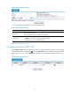
Table 19 Information about protected IP address entries
Item Descri
p
tion
Protected IP
IP addresses protected by the TCP proxy feature.
Port Number
Destination port of the TCP connection.
The option any specifies that TCP proxy services TCP connection requests to
any port of the server at the destination IP address.
Type The protected IP address entries can be static or dynamic.
Lifetime(min)
Lifetime for the IP address entry under protection. This item is displayed as –
for static IP address entries.
When the time reaches 0, the protected IP address entry will be deleted.
Number of Rejected
Amount of requests for TCP connection requests matching the protected IP
address entry but were proved to be illegitimate.
Return to TCP proxy configuration task list.
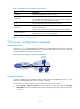
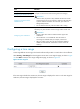
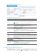
TCP proxy configuration example
Network requirements
As shown in Figure 47, configure bidirectional TCP proxy on the LB module to protect Server A, Server B,
and Server C against SYN flood attacks. Add a protected IP address entry for Server A manually and
configure dynamic TCP proxy for the other servers.
Figure 47 Network diagram for TCP proxy configuration
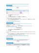
Configuration procedure
# Assign IP addresses for the interfaces and then add interface Ten-GigabitEthernet 0/0.1 to zone
Untrust, and Ten-GigabitEthernet 0/0.2 to zone Trust. (Omitted)
# Set the TCP proxy mode to bidirectional and enable TCP proxy for zone Untrust.
• Select Security > Intrusion Detection from the navigation tree and then select the TCP Proxy
Configuration tab. Select the bidirectional mode and enable TCP proxy for zone Untrust as shown
in Figure 48.
LB
XGE0/0.1
10.0.0.1/24
XGE0/0.2
20.0.0.1/24
IP network
Server A
Server CServer B
20.0.0.10/24
Untrust
Trust