HP Load Balancing Module System Maintenance Configuration Guide Part number: 5998-2688 Document version: 6PW101-20120217
Legal and notice information © Copyright 2012 Hewlett-Packard Development Company, L.P. No part of this documentation may be reproduced or transmitted in any form or by any means without prior written consent of Hewlett-Packard Development Company, L.P. The information contained herein is subject to change without notice.
Contents System maintenance and debugging ························································································································· 1 Ping ····················································································································································································· 1 Introduction ················································································································································
Log report ········································································································································································ 39 Displaying system logs ·········································································································································· 39 Displaying connection limit logs ·························································································································· 41 Displ
Introduction to FTP ················································································································································· 66 Operation of FTP ··················································································································································· 66 Configuring the FTP client ············································································································································· 67 Est
System maintenance and debugging You can use the ping command and the tracert command to verify the current network connectivity, and use the debug command to enable debugging and thus to diagnose system faults based on the debugging information. NOTE: The LB module supports configuring ping, tracert, and system debugging only at the command line interface (CLI).
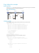
Ping configuration example Network requirements As shown in Figure 1, check whether LB and Device B can reach each other. If they can reach each other, get the detailed information of routes from LB and Device B. Figure 1 Ping network diagram SecBlade Device A 1.1.1.1/24 Device B 1.1.2.1/24 1.1.1.2/24 ECHO-REQUEST (NULL) 1.1.2.2/24 ECHO-REQUEST 1st=1.1.2.1 ECHO-REPLY ECHO-REPLY 1st=1.1.2.1 2nd=1.1.2.2 3rd=1.1.1.2 4th=1.1.1.1 ECHO-REPLY 1st=1.1.2.1 2nd=1.1.2.2 1st=1.1.2.1 2nd=1.1.2.2 3rd=1.1.1.
1.1.1.1 Reply from 1.1.2.2: bytes=56 Sequence=3 ttl=254 time=1 ms Record Route: 1.1.2.1 1.1.2.2 1.1.1.2 1.1.1.1 Reply from 1.1.2.2: bytes=56 Sequence=4 ttl=254 time=1 ms Record Route: 1.1.2.1 1.1.2.2 1.1.1.2 1.1.1.1 Reply from 1.1.2.2: bytes=56 Sequence=5 ttl=254 time=1 ms Record Route: 1.1.2.1 1.1.2.2 1.1.1.2 1.1.1.1 --- 1.1.2.2 ping statistics --5 packet(s) transmitted 5 packet(s) received 0.00% packet loss round-trip min/avg/max = 1/11/53 ms The principle of ping –r is as shown in Figure 1. 1.
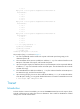
Figure 2 Tracert diagram The tracert function is implemented through ICMP, as shown in Figure 2: 1. The source (Device A) sends a packet with a TTL value of 1 to the destination (Device D). The UDP port of the packet is a port number that will not be used by any application of the destination. 2. The first hop (Device B) (the Layer 3 device that first receives the packet) responds by sending a TTL-expired ICMP error message to the source, with its IP address 1.1.1.2 encapsulated.
Tracert configuration Follow the step below to configure tracert: To do… Use the command… Display the routes from source to destination tracert [ -a source-ip | -f first-ttl | -m max-ttl | -p port | -q packet-number | -w timeout ] * host Remarks Required Use either approach The tracert command is applicable in an IPv4 network. Available in any view System debugging Introduction to system debugging The device provides various debugging functions.
the debugging function that was used, or use the undo debugging all command to disable all the debugging functions. Output of debugging information depends on the configurations of the information center and the debugging commands of each protocol and functional module. Debugging information is commonly output to a terminal (including console or VTY) for display. You can also output debugging information to other destinations. For more information, see the chapter “Information center configuration.
Request time out Request time out Request time out --- 1.1.2.2 ping statistics --5 packet(s) transmitted 0 packet(s) received 100.00% packet loss # LB and Device B cannot reach each other. Use the tracert command to determine failed nodes. system-view [LB] ip ttl-expires enable [LB] ip unreachables enable [LB] tracert 1.1.2.2 traceroute to 1.1.2.2(1.1.2.2) 30 hops max,40 bytes packet, press CTRL_C to bre ak 1 1.1.1.
Information center configuration NOTE: The LB module supports configuring information center only at the command line interface (CLI). Information center overview Introduction to information center The information center classifies and manages system information, offering powerful support for network administrators and developers to monitor network performance and troubleshoot network problems.
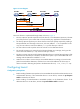
Figure 5 Information center diagram System information Information channel Output destination Log information 0 Console console 1 Trap information Monitor monitor 2 Log host loghost 3 Trap buffer trapbuffer Debugging information 4 Log buffer logbuffer 5 SNMP module snmpagent 6 Web interface channel6 7 channel7 8 channel8 9 channel9 Log file NOTE: By default, the information center is enabled.
Table 1 Severity description Severity Severity value Description Corresponding keyword in commands Emergency 0 The system is unusable.
Information channel number Default channel name Default output destination Description 8 channel8 Not specified Receives log, trap, and debugging information. 9 channel9 Log file Receives log, trap, and debugging information. NOTE: Configurations for the information output destinations function independently and take effect only after the information center is enabled.
Output destination Modules allowed Trap buffer LOG DEBUG TRAP Enabled/ disabled Severity Enabled/ disabled Severity Enabled/ disabled Severity default (all modules) Disabled Informatio nal Enabled Informatio nal Disabled Debug Log buffer default (all modules) Enabled Informatio nal Disabled Debug Disabled Debug SNMP module default (all modules) Disabled Debug Enabled Informatio nal Disabled Debug Web interface default (all modules) Enabled Debug Enabled Debug Disable
Note that the priority field takes effect only when the information has been sent to the log host. timestamp Times tamp records the time when system information is generated to allow users to check and identify system events. The time stamp of the system information sent from the information center to the log host is with a precision of milliseconds.
%% (vendor ID) This field indicates that the information is generated by an HP device. It is displayed only when the system information is sent to a log host in the format of HP. vv This field is a version identifier of syslog, with a value of 10. It is displayed only when the output destination is log host. module The module field represents the name of the module that generates system information. You can enter the info-center source ? command in system view to view the module list.
Task Remarks Outputting system information to the console Optional Outputting system information to a monitor terminal Optional Outputting system information to a log host Optional Outputting system information to the trap buffer Optional Outputting system information to the log buffer Optional Outputting system information to the SNMP module Optional Outputting system information to the web interface Optional Saving system information to a log file Optional Configuring synchronous informa
To do… Use the command… Remarks Optional Enable the monitoring of system information on the console terminal monitor Enable the display of debugging information on the console terminal debugging Enable the display of log information on the console terminal logging Enable the display of trap information on the console terminal trapping Enabled on the console and disabled on the monitor terminal by default.
To do… Use the command… Remarks Required Enable the monitoring of system information on a monitor terminal terminal monitor Enable the display of debugging information on a monitor terminal terminal debugging Enable the display of log information on a monitor terminal terminal logging Enable the display of trap information on a monitor terminal terminal trapping Enabled on the console and disabled on the monitor terminal by default.
To do… Use the command… Remarks Required Specify a log host and configure the related output parameters info-center loghost host-ipv4-address [ port port-number ] [ channel { channel-number | channel-name } | facility local-number ] * By default, the system does not output information to a log host. If you specify to output system information to a log host, the system uses channel 2 (loghost) by default.
Outputting system information to the log buffer NOTE: You can configure to output log, trap, and debugging information to the log buffer, but the log buffer receives the log and debugging information only, and discards the trap information.
To do… Use the command… Remarks Name the channel with a specified channel number info-center channel channel-number name channel-name Optional Configure the channel through which system information can be output to the SNMP module info-center snmp channel { channel-number | channel-name } Configure the output rules of the system information info-center source { module-name | default } channel { channel-number | channel-name } [ debug { level severity | state state } * | log { level severity | state
To do… Use the command… Remarks Optional Configure the format of the time stamp info-center timestamp { debugging | log | trap } { boot | date | none } The time stamp format for log, trap and debugging information is date by default. NOTE: You can configure to output log, trap and debugging information to a channel.
NOTE: • To ensure that the device works normally, use the info-center logfile size-quota command to set a log file to be no smaller than 1 MB and no larger than 10 MB. • The info-center logfile switch-directory command is always used when you back up or move files. The configuration will be invalid after system reboot or the active standby switchover.
To do… Use the command… Remarks Required Disable the port from generating link up/down logging information undo enable log updown By default, all ports are allowed to generate link up/down logging information when the port state changes. NOTE: A port enabled with this feature does not output link up/down log information, and cannot be monitored conveniently. Therefore, HP recommends that you use the default configuration in normal cases.
Figure 6 Network diagram for outputting log information to a UNIX log host Configuration procedure Before the configuration, make sure that there is a route between LB and PC. 1. Configure the device # Enable information center. system-view [Sysname] info-center enable # Specify the host with IP address 1.2.0.1/16 as the log host, use channel loghost to output log information (optional, loghost by default), and use local4 as the logging facility. [Sysname] info-center loghost 1.2.0.
NOTE: Be aware of the following issues while editing file /etc/syslog.conf: • Comments must be on a separate line and begin with the # sign. • No redundant spaces are allowed after the file name. • The logging facility name and the information level specified in the /etc/syslog.conf file must be identical to those configured on the device using the info-center loghost and info-center source commands; otherwise the log information may not be output properly to the log host. Step 4: After log file info.
CAUTION: Because the default system configurations for different channels are different, first disable the output of log, trap, and debugging information of all modules on the specified channel (loghost in this example), and then configure the output rule as needed so that unnecessary information will not be output. # Configure the information output rule: allow log information of all modules with severity equal to or higher than informational to be output to the log host.
• The source modules are ARP and IP. Figure 8 Network diagram for sending log information to the console Configuration procedure # Enable information center. system-view [Sysname] info-center enable # Use channel console to output log information to the console (optional, console by default). [Sysname] info-center console channel console # Disable the output of log, trap, and debugging information of all modules on channel console.
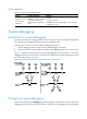
Log management The log management feature enables you to store the system messages or logs generated by actions such as packet filtering to the log buffer or send them to the log hosts. The analysis and archiving of the logs can enable you to check the security holes of the firewall, when and who try to disobey security policies, and the types of the network attacks. The real-time logs can also be used to detect the ongoing attacks.
Figure 9 Syslog Table 5 Syslog configuration items Item Description Log Buffer Size Set the number of syslogs that can be stored in the log buffer. Clear Log To clear the logs in the log buffer, click this button. Log Host 1 Log Host IP Address Log Host 2 Log Host 3 Set the IPv4 addresses and port number of the syslog log hosts. The log information can be reported to the specified remote log hosts in the format of syslog, and you can specify up to four syslog log hosts.
Item Description Set the refresh period on the log information displayed on the log report web interface. You can select manual refresh or automatic refresh: Refresh Period • Manual: You need to refresh the web interface when displaying log report information. • Automatic: You can select to refresh the web page every 10 seconds, 30 seconds, 1 minute, 5 minutes, or 10 minutes.
Field Description Operator Indicates the reason why a flow has ended Reserved For future applications Table 7 Packet format in flow logging version 3.0 Field Description Prot Protocol carried over IP Operator Indicates the reason why a flow has ended.
Figure 10 Flow logging Table 8 Flow logging configuration items Item Description Set the version of flow logging, including 1.0 and 3.0. Version IMPORTANT: Configure the flow logging version according to the capacity of the LB module that receives logs. If the log receiving card does not support flow logging of a certain version, the card cannot resolve the logs received. Set the source IP address of flow logging packets.
Item Description Log Host 1 Log Host Configura tion Set the IPv4 addresses, and port number and the VPN instance of the Userlog log host to encapsulate flow logs in UDP packets and send them to the specified userlog log host. The log host can analyze and display the flow logs to remotely monitor the LB module. You can specify up to two different userlog log hosts. If you specify two log hosts with the same IP address, the system will prompt an error message.
Configuring flow logging version Configure the flow logging version according to the receiver capability. A receiver cannot resolve flow logs correctly if it does not support the version of the flow logs. Follow these steps to configure flow logging version: To do … Use the command… Remarks Enter system view system-view — Configure flow logging version userlog flow export version version-number Optional The default flow logging version is 1.
Exporting flow logs to a log server Follow these steps to export flow logs to an IPv4 log server: To do… Use the command… Remarks Enter system view system-view — Configure the IPv4 address and UDP port number of the log server userlog flow export host ipv4-address udp-port Required Not configured by default. NOTE: You can select at most two log servers from three types of log servers to receive flow logs for each device.
Figure 12 Network diagram for flow logging 2. Configuration procedure • Configuration on the LB module. # Configure IP addresses for the interfaces according to the network diagram, and make sure that there are available routes between User and the LB module and between the LB module and the log server. (The configuration procedure is omitted here.) # Set the flow logging version to 3.0. system-view [LB] userlog flow export version 3 # Export User's flow logs to the log server with IP address 1.
• Analysis: Both of the export approaches are configured. • Solution: Restore to the default, and then configure the IP address and UDP port number of the log server. Session logging NOTE: The LB module supports configuring session logging only on the web interface.
Configuring a session logging policy Select Log Report > Session Log > Log Policy from the navigation tree to display existing session logging policies, as shown in Figure 13. Then, click Add to enter the session logging policy configuration page, as shown in Figure 14. Figure 13 Session logging policy list Figure 14 Create a session logging policy Configuration items for configuring a session logging policy Item Description Source Zone Specify the source zone and destination zone.
Figure 15 Global configuration page Configuration items for setting session logging thresholds Item Description Set the time threshold for outputting session logging entries. Time Threshold Traffic Threshold With this argument set, log entries will be output for sessions whose lifetimes reach the specified time threshold. Set the traffic threshold for outputting session logging entries. It can be in number of packets or bytes.
Figure 16 Operation log configuration page Table 10 System log configuration items Item Description Time/Date Displays the time when the system logs are generated. Source Displays the module that generates the system logs. Level Displays the severity level of the system logs. For more information about severity levels, see Table 11. Description Displays the contents of the system logs. Table 11 System log severity level Severity level Description Value Emergency The system is unavailable.
Displaying connection limit logs Select Log Report > Report > Connection Limit Log from the navigation tree to enter the page as shown in Figure 17. Figure 17 Connection limit log configuration page Table 12 Connection limit log configuration items Item Description Time/Date Displays the time when the connection limit logs are generated.
Figure 18 Attack prevention log configuration page Table 13 Attack prevention log configuration items Item Description Time Displays the time when attacks are detected. Type Displays the attack type. Interface Displays the interface that receives the attack packets. Source IP Displays the source IP address of the attack packets. Source MAC Displays the source MAC address of the attack packets. Destination IP Displays the destination IP address of the attack packets.
Table 14 Blacklist log configuration items Item Description Time/Date Displays the time when the blacklist members are generated. Mode Displays whether the blacklist members are newly added or removed. Source IP Displays the IP addresses of the blacklist members. Displays the reasons why the addresses are added to the blacklist, including manual add and automatic add: Reason • Automatic add means that the system automatically adds the source IP address to the blacklist.
Item Description Displays the flow information. • If the protocol type is TCP or UDP, the displayed flow information is source IP address:source port-->destination IP address:destination port, for example, 1.1.1.2:1026-->1.1.2.10:69. Flow Information • If the protocol type is ICMP, the displayed flow information is source IP address-->destination IP address,ICMP type (ICMP code), for example, 1.1.1.2-->1.1.2.10, echo(8).
Figure 22 Flow logging 3.0 log report Table 16 Flow logging 1.0 configuration items Item Description Time/Date Displays the time and date when a flow log was generated. Protocol Type Displays the protocol type of a flow log. Displays flow information: • If the protocol type is TCP or UDP, the displayed flow information is source IP Flow Information address:source port-->destination IP address:destination port, for example, 1.1.1.2:1026-->1.1.2.10:69.
Table 17 Flow logging 3.0 configuration items Item Description Time/Date Displays the time and date when a flow log was generated. Protocol Type Displays the protocol type of a flow. Displays the flow information. • If the protocol type is TCP or UDP, the displayed flow information is source IP Flow Information address:source port-->destination IP address:destination port, for example, 1.1.1.2:1026-->1.1.2.10:69.
SNMP configuration NOTE: The LB module supports configuring SNMP only at the command line interface (CLI). SNMP overview The Simple Network Management Protocol (SNMP) is an Internet standard protocol widely used for a management station to access and operate the devices on a network, regardless of their vendors, physical characteristics and interconnect technologies.
SNMP provides the following four basic operations: • Get—The NMS retrieves SNMP object nodes in an agent MIB. • Set—The NMS modifies the value of an object node in the agent MIB. • Trap—The SNMP agent sends traps to report events to the NMS. • Inform—The NMS sends alarms to other NMSs. SNMP protocol versions HP SNMP agents support three SNMP protocol versions: SNMPv1, SNMPv2c, and SNMPv3. • SNMPv1 uses community names for authentication.
To do… Use the command… Remarks Optional Enable the SNMP agent service snmp-agent Configure SNMP agent system information snmp-agent sys-info { contact sys-contact | location sys-location | version { all | { v1 | v2c | v3 }* } } Configure a local engine ID for an SNMP entity snmp-agent local-engineid engineid Create or update the MIB view content for an SNMP agent snmp-agent mib-view { excluded | included } view-name oid-tree [ mask mask-value ] Create an SNMPv3 group and specify its access right
To do… Use the command… Remarks Optional Disabled by default Enable the SNMP agent service snmp-agent You can also enable the SNMP by using any command that begins with snmp-agent.
The SNMP module sends these logs to the information center as informational messages. You may output these messages to certain destinations, for example, the console and the log buffer by configuring the information center to output informational messages to these destinations. For more information about the information center, see the chapter “Information center configuration.
To do… Use the command… Remarks Enable the trap function globally snmp-agent trap enable | bgp | configuration | flash | ospf [ process-id ] [ ifauthfail | ifcfgerror | ifrxbadpkt | ifstatechange | iftxretransmit | lsdbapproachoverflow | lsdboverflow | maxagelsa | nbrstatechange | originatelsa | vifcfgerror | virifauthfail | virifrxbadpkt | virifstatechange | viriftxretransmit | virnbrstatechange ] * | standard [ authentication | coldstart | linkdown | linkup | warmstart ] * | system | vrrp [ authfailur
To do… Use the command… Remarks Configure the source address for traps snmp-agent trap source interface-type { interface-number | interface-number.subnumber } Optional Extend the standard linkUp/linkDown traps defined in RFC snmp-agent trap if-mib link extended Configure the size of the trap send queue snmp-agent trap queue-size size Configure the holding time of the traps in the queue snmp-agent trap life seconds Optional Standard linkUp/linkDown traps defined in RFC are used by default.
SNMP configuration examples SNMPv1/SNMPv2c configuration example Network requirements As shown in Figure 25, the NMS connects to the agent through an Ethernet. The NMS at 1.1.1.2/24 uses SNMPv1 or SNMPv2c to manage the SNMP agent at 1.1.1.1/24, and the agent automatically sends traps to the NMS to report events. Figure 25 Network diagram for SNMPv1/v2c Configuration procedure 1. Configure the SNMP agent # Configure the IP address of the agent as 1.1.1.
• Execute the shutdown or undo shutdown command to an idle interface on the agent, and the NMS receives the corresponding trap. SNMPv3 configuration example Network requirements • As shown in Figure 26, the NMS connects to the agent through an Ethernet. The IP address of the NMS is 1.1.1.2/24, and the IP address of the agent is 1.1.1.1/24. • The NMS monitors and manages the interface status of the agent using SNMPv3. The agent reports errors or faults to the NMS.
key, privacy mode, and privacy key. In addition, the timeout time and number of retries should also be configured. The user can inquire and configure the device through the NMS. NOTE: The configurations on the agent and the NMS must match. 3. Verify the configuration • After the above configuration, an SNMP connection is established between the NMS and the agent. The NMS can get and configure the values of some parameters on the agent through MIB nodes.
[Sysname] snmp-agent log get-operation [Sysname] snmp-agent log set-operation The following log information is displayed on the terminal when the NMS performs the Get operation to the agent. • %Jan 1 02:49:40:566 2006 Sysname SNMP/6/GET: seqNO = <10> srcIP = <1.1.1.2> op = node = value=<> The following log information is displayed on the terminal when the NMS performs the Set operation to the agent.
File system management NOTE: The LB module supports configuring file management at the CLI only. File system management overview Files such as host software and configuration files that are necessary for the operation of the device are saved in the storage media of the device. You can manage files on your device through these operations: Managing directories, Managing files, Performing batch operations, Managing storage media, and Setting prompt modes.
Format Description Length Example drive:/[path]/filename Specifies a file in the specified storage medium on the device. drive represents the storage medium name, which is usually cf. If there is only one storage medium on the device, you do not need to provide information about the storage medium. If multiple storage media exist on the device, you must provide the related information to identify the storage medium. 1 to 135 characters cfa0:/test/a.cfg indicates a file named a.
Removing a directory To do… Use the command… Remove a directory rmdir directory Remarks Required Available in user view NOTE: • Before you remove a directory, you must delete all the files and the subdirectory in this directory. To delete a file, see the delete command; to delete a subdirectory, see the rmdir command. • The rmdir command automatically deletes the files in the recycle bin in the current directory.
Copying a file To do… Use the command… Copy a file copy fileurl-source fileurl-dest Remarks Required Available in user view Moving a file To do… Use the command… Move a file move fileurl-source fileurl-dest Remarks Required Available in user view Deleting a file To do… Use the command… Move a file to the recycle bin or delete it permanently delete [ /unreserved ] file-url Remarks Required Available in user view CAUTION: • The files in the recycle bin still occupy storage space.
Performing batch operations A batch file is a set of executable commands. Executing a batch file is the same as executing the commands in the batch file one by one. Before executing a batch file, edit the batch file on your PC, and then download it to the device. If the suffix of the file is not .bat, use the rename command to change the suffix to .bat.
• An unmounted device is in the disconnected state, and can be removed safely. If you unplug a storage medium without unmounting it, files on the storage medium or even the storage medium may be damaged. • An unmounted storage medium can be used only when it is mounted again.
CAUTION: • The fdisk device [ partition-number ] command clears all data in a CF card or a USB disk. Save the files in the CF card or a USB disk before partitioning it. • The fdisk device [ partition-number ] command adds or reduces partitions. You should reconfigure the paths of the application files as needed. • If the device starts up from a CF card, the startup file and the configuration file must be in the first partition of the CF card.
6 -rw- 13713928 Apr 26 2000 14:57:14 lb_0521.bin 7 -rw- 13685000 May 01 2000 08:05:34 b87-lb.bin 8 -rw- 11357840 Apr 26 2000 12:21:26 b504-lb.bin 9 -rw- 17133 May 03 2000 10:38:52 1000.txt 252904 KB total (188368 KB free) # Create new folder mytest in the test directory. cd test mkdir mytest %Created dir cfa0:/test/mytest. # Display the current working directory.
FTP configuration NOTE: The LB module supports FTP configuration only in the command line interfaces (CLIs). FTP overview Introduction to FTP The File Transfer Protocol (FTP) is an application layer protocol used to share files between server and client over a TCP/IP network. FTP uses TCP ports 20 and 21. Port 20 is used to transmit data, and port 21 is used to transmit control commands. For more information about FTP basic operations, see RFC 959.
Device Configuration Remarks PC (FTP server) Enable FTP server on the PC, and configure the username, password, user privilege level, and so on. — When the LB module serves as the FTP server, you need to perform the following configuration: Table 20 Configuration when the LB module serves as the FTP server Device Configuration Remarks Disabled by default. Enable the FTP server function You can use the display ftp-server command to view the FTP server configuration on the LB module.
The FTP client follows these rules to select the source IP address of packets sent to the FTP server: • If no source IP address is specified, the IP address of the output interface of the route to the server is used as the source IP address. • The source IP address specified with the ftp client source or ftp command is used. • If you first use the ftp client source command to specify a source IP address and then use the ftp command to specify another source IP address, the latter is used.
To do… Use the command… Remarks Create a directory on the remote FTP server mkdir directory Optional Remove the specified working directory on the remote FTP server rmdir directory Optional Operating the files on the FTP server After the LB module serving as the FTP client has established a connection with an FTP server, you can upload a file to or download a file from the FTP server under the authorized directory of the FTP server by following these steps.
Using another username to log in to the FTP server After the LB module serving as the FTP client has established a connection with the FTP server, you can use another username to log in to the FTP server. For more information about establishing an FTP connection, see “Establishing an FTP connection.
FTP client configuration example Network requirements • As shown in Figure 29, use LB module as an FTP client and PC as the FTP server. Their IP addresses are 10.2.1.1/16 and 10.1.1.1/16 respectively. LB module and PC are reachable to each other. • LB module downloads a boot file from PC for upgrade, and uploads the configuration file to PC for backup. • On PC, an FTP user account has been created for the FTP client, with the username abc and the password abc.
# Specify newest.bin as the main boot file to be used at the next startup. boot-loader file newest.bin main # Reboot LB module, and the boot file is updated at the system reboot. reboot CAUTION: The boot file used at the next startup must be saved under the root directory of the storage medium (For a device that has been partitioned, the boot file must be saved on the first partition). You can copy or move a file to the root directory of the storage medium.
Configuring authentication and authorization on the FTP server To allow an FTP user to access certain directories on the FTP server, you need to create an account for the user, authorize the user to access the directories and configure a password for the user. Make the following configuration to perform authentication and authorization on a local FTP user. To authenticate remote FTP users, you need to configure authentication, authorization and accounting (AAA).
Set the username to abc and the password to abc for the FTP client to log in to the FTP server. • Figure 30 Upgrading using the FTP server Configuration procedure Configure LB module (FTP server) 1. # Create an FTP user account abc, set its password to abc and the user privilege level to level 3 (the manage level). Allow user abc to access the root directory of the CFa0, and specify abc to use FTP.
ftp> put newest.bin ftp> bye NOTE: • You can take the same steps to upgrade configuration file with FTP. When upgrading the configuration file with FTP, put the new file under the root directory of the storage medium (For a device that has been partitioned, the configuration file must be saved on the first partition.). • After you finish transferring the Boot ROM program through FTP, you must execute the bootrom update command to upgrade the Boot ROM. 3. Upgrade LB module # Specify newest.
TFTP configuration NOTE: The LB module supports TFTP configuration only in the CLIs. TFTP overview Introduction to TFTP The Trivial File Transfer Protocol (TFTP) provides functions similar to those provided by FTP, but it is less complex than FTP in interactive access interface and authentication. It is more suitable in environments where complex interaction is not needed between client and server. TFTP uses the UDP port 69 for data transmission.
Table 21 Configuration when the LB module serves as the TFTP client Device Configuration Remarks • Configure the IP address and routing function, and ensure that the LB (TFTP client) route between the LB module and the TFTP server is available. • Use the tftp command to establish a connection to the remote TFTP — server to upload/download files to/from the TFTP server PC (TFTP server) Enable TFTP server on the PC, and configure the TFTP working directory.
To do… Use the command… Remarks Optional Specify the source IP address of sent TFTP packets tftp client source { interface interface-type interface-number | ip source-ip-address } By default, the source IP address is determined by the route from the TFTP client to the TFTP server.
CAUTION: If the available memory space of the LB module is not enough, use the fixdisk command to clear the memory or use the delete /unreserved file-url command to delete the files not in use and then perform the following operations. # Download application file newest.bin from PC. tftp 1.2.1.1 get newest.bin # Upload a configuration file config.cfg to the TFTP server. tftp 1.2.1.1 put config.cfg configback.cfg # Specify newest.bin as the main boot file to be used at the next startup.
IP performance optimization configuration NOTE: The LB module supports IP performance optimization configuration only in the command line interfaces (CLIs). IP performance optimization overview In some network environments, you can adjust the IP parameters to achieve best network performance.
Configuring the TCP send/receive buffer size Follow these steps to configure the TCP send/receive buffer size: To do… Use the command… Remarks Enter system view system-view — Configure the size of TCP receive/send buffer tcp window window-size Optional 8 KB by default. Configuring TCP timers You can configure the following TCP timers: • synwait timer: When sending a SYN packet, TCP starts the synwait timer.
A host may have only a default route to the default gateway in its routing table after startup. The default gateway will send ICMP redirect packets to the source host, telling it to reselect a correct next hop to send the subsequent packets, if the following conditions are satisfied: • The receiving and forwarding interfaces are the same. • The selected route has not been created or modified by ICMP redirect packet. • The selected route is not the default route of the LB module.
• If an attacker sends abnormal traffic that causes the device to generate ICMP destination unreachable packets, end users may be affected. To prevent such problems, you can disable the LB module from sending ICMP error packets.
Support and other resources Contacting HP For worldwide technical support information, see the HP support website: http://www.hp.
Conventions This section describes the conventions used in this documentation set. Command conventions Convention Description Boldface Bold text represents commands and keywords that you enter literally as shown. Italic Italic text represents arguments that you replace with actual values. [] Square brackets enclose syntax choices (keywords or arguments) that are optional. { x | y | ... } Braces enclose a set of required syntax choices separated by vertical bars, from which you select one.
Network topology icons Represents a generic network device, such as a router, switch, or firewall. Represents a routing-capable device, such as a router or Layer 3 switch. Represents a generic switch, such as a Layer 2 or Layer 3 switch, or a router that supports Layer 2 forwarding and other Layer 2 features. Represents a LB module. Port numbering in examples The port numbers in this document are for illustration only and might be unavailable on your device.
Index CDEFILMPRST Information center configuration examples,23 C Information center overview,8 Configuring ICMP to send error packets,81 IP performance optimization overview,80 Configuring information center,14 Configuring SNMP basic parameters,48 L Configuring SNMP logging,50 Log report,39 Configuring SNMP traps,51 M Configuring syslog,28 Managing directories,59 Configuring TCP attributes,80 Managing files,60 Configuring the FTP client,67 Managing storage media,62 Configuring the FTP serve