
R3204P16-HP Load Balancing Module System Maintenance Configuration Guide-6PW101

36
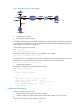
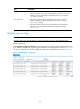
Figure 12 Network diagram for flow logging
2. Configuration procedure
• Configuration on the LB module.
# Configure IP addresses for the interfaces according to the network diagram, and make sure that there
are available routes between User and the LB module and between the LB module and the log server.
(The configuration procedure is omitted here.)
# Set the flow logging version to 3.0.
<LB> system-view
[LB] userlog flow export version 3
# Export User's flow logs to the log server with IP address 1.2.3.6:2000.
[LB] userlog flow export host 1.2.3.6 2000
# Configure the source IP address of UDP packets carrying flow logs as 2.2.2.2 so that the log server can
identify that the actions described in the log were on the LB module or on other devices.
[LB] userlog flow export source-ip 2.2.2.2
3. Configuration verification
# Display the configuration and statistics about flow logs.
<LB> display userlog export
nat:
No userlog export is enabled
flow:
Export Version 3 logs to log server : enabled
Source address of exported logs : 2.2.2.2
Address of log server : 1.2.3.6 (port: 2000)
total Logs/UDP packets exported : 112/87
Logs in buffer : 6
Troubleshooting flow logging
Symptom 1: No flow log is exported
• Analysis: Neither of the export approach is specified.
• Solution: Configure to export the flow logs to the information center or to the log server.
Symptom 2: Flow logs cannot be exported to log server