HP Load Balancing Module System Management Configuration Guide Part number: 5998-2683 Document version: 6PW101-20120217
Legal and notice information © Copyright 2012 Hewlett-Packard Development Company, L.P. No part of this documentation may be reproduced or transmitted in any form or by any means without prior written consent of Hewlett-Packard Development Company, L.P. The information contained herein is subject to change without notice.
Contents Overview ······································································································································································ 1 Features ·············································································································································································· 1 Application scenarios ·····················································································································
NMS login example······················································································································································· 44 Logging in to the LB module from the network device ····························································································· 46 Logging in to the LB module from the network device ······························································································· 46 Configuring the AUX user interface of t
User levels ······································································································································································· 76 Configuring local users and displaying online users in the web interface ······························································ 76 Configuring a local user ······································································································································· 76 Local user configuration e
NTP configuration examples ······································································································································· 105 Configuring NTP client/server mode ················································································································ 105 Configuring the NTP symmetric mode ·············································································································· 106 Configuring NTP broadcast mode·············
Returning to user view ········································································································································· 138 Using the CLI online help ············································································································································ 138 Typing commands ························································································································································ 139 Edi
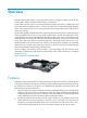
Overview HP load balancing (LB) module, a leading LB product of HP, is designed for data centers of carriers, portal websites, large and medium-sized enterprises, and industries. The LB module can be installed on an HP A7500/A9500/A12500 series switch or A8800 router, and can be deployed at the distribution layer or core layer of a data center. The LB module equally distributes clients' access requests to the servers in the data center, thus ensuring the data center's response speed and service continuity.
• Rich load balancing scheduling algorithms. A LB module supports multiple load balancing scheduling algorithms for different application scenarios, such as round robin, weighted round robin, least connections, weighted least connections, random, weighted random, source address hashing, destination address hashing, source port hashing and UDP packet payload hashing. These algorithms are applicable to Layer 4-7 load balancing. Besides, Layer 7 load balancing supports algorithms of HTTP content and RTSP URL.
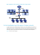
Figure 2 Application in small- and medium-sized data centers of campus networks For link load balancing at the egress of campus networks A campus network uses two physical links to connect to two carrier networks, ISP1 and ISP2.
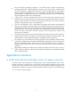
Figure 3 Application for link load balancing at the egress of campus networks Internet ISP1 ISP2 ISP1 router ISP2 router LB+Switch Switch User1 User2 User3 User4 User5 User6 In large data centers of carriers and portal websites Generally, load balancing is implemented in large data centers of carriers and portal websites. In the scenario, one or two LB modules are installed on each stateful failover-capable distribution layer switch, and VRRP is enabled on the LB modules for high reliability.
Figure 4 Application in large data centers of carriers and portal websites 5
Login methods Login methods You can log in to a device in the following ways. Table 1 Login methods Login method Logging in through the console port Default state By default, you can log in to a device through the console port, the authentication mode is None (no username or password required), and the user privilege level is 3. By default, you cannot log in to a device through Telnet.
User interface overview User interfaces, or lines allow you to manage and monitor sessions between the terminal and device when you log in to the device through the console port or through Telnet. One user interface corresponds to one user interface view where you can configure a set of parameters, such as whether to authenticate users at login, whether to redirect the requests to another device, and the user privilege level after login.
• VTYs are numbered from 0 in the ascending order, with a step of 1.
CLI login Overview The CLI enables you to interact with a device by typing text commands. At the CLI, you can instruct your device to perform a given task by typing a text command and then pressing Enter to submit it to your device. Compared with the graphical user interface (GUI) where you can use a mouse to perform configuration, the CLI allows you to input more information in one command line. You can log in to the device at the CLI through the console port or Telnet,.
The port properties of the hyper terminal must be the same as the default settings of the console port shown in the following table. Setting Default Bits per second 9,600 bps Flow control None Parity None Stop bits 1 Data bits 8 Login procedure 1. As shown in Figure 5, use the console cable shipped with the device to connect the PC and the device. Plug the DB-9 connector of the console cable into the serial port of the PC, and plug the RJ-45 connector into the console port of your device.
Figure 6 Connection description Figure 7 Specify the serial port used to establish the connection 11
Figure 8 Set the properties of the serial port 3. Turn on the device. You are prompted to press Enter if the device successfully completes the power-on self test (POST). A prompt such as appears after you press Enter, as shown in Figure 9.
Figure 9 Configuration page 4. Execute commands to configure the device or check the running status of the device. To get help, type ?. Console login authentication modes The following authentication modes are available for console port login: none, password, and scheme. • none—Requires no username and password at the next login through the console port. This mode is insecure. • password—Requires password authentication at the next login through the console port.
Authentication mode Configuration Remarks Configure the authentication scheme Configure a RADIUS scheme Remote AAA authentication Scheme Select an authentic ation scheme Configure the AAA scheme used by the domain Configure the username and password on the AAA server Local authentication For more information, see “Configuring scheme authentication for console login.
Figure 10 Configuration page Configuring password authentication for console login Configuration prerequisites You have logged in to the device. By default, you can log in to the device through the console port without authentication and have user privilege level 3 after login. For information about logging in to the device with the default configuration, see “Configuration requirements.
To do… Configure common settings for console login Use the command… Remarks Optional — See “Configuring common settings for console login (optional).” When you log in to the device through the console port after configuration, you are prompted to enter a login password. A prompt such as appears after you input the password and press Enter, as shown in Figure 11.
To do… Use the command… Remarks Required Specify the scheme authentication mode authentication-mode scheme Whether local or RADIUS authentication is adopted depends on the configured AAA scheme. By default, users that log in through the console port are not authenticated.
Figure 12 Configuration page Configuring common settings for console login (optional) Follow these steps to configure common settings for console port login To do… Use the command… Remarks Enter system view system-view — Enable display of copyright information copyright-info enable Enter console user interface view user-interface console number 18 Optional Enabled by default.
Use the command… To do… Remarks Optional Configure the baud rate speed speed-value Configure the parity check mode parity { even | mark | none | odd | space } By default, the transmission rate is 9600 bps. Transmission rate is the number of bits that the device transmits to the terminal per second. Optional none by default. Optional Configure the stop bits By default, the stop bits of the console port is 1. stopbits { 1 | 1.
Use the command… To do… Set the maximum number of lines on the next screen. screen-length screen-length Set the size of history command buffer history-command max-size value Remarks Optional By default, the next screen displays 24 lines. A value of 0 disables the function. Optional By default, the buffer saves 10 history commands at most. Optional Set the idle-timeout timer idle-timeout minutes [ seconds ] The default idle-timeout is 10 minutes.
• On a device that serves as the Telnet client, you can log in to a Telnet server to perform operations on the server. • On a device that serves as the Telnet server, you can configure the authentication mode and user privilege level for Telnet users. By default, scheme authentication is adopted for Telnet login.
By default, you can log in to the device through the console port without authentication and have user privilege level 3 after login. For information about logging in to the device with the default configuration, see “Configuration requirements.
Figure 14 Configuration page Configuring password authentication for Telnet login Configuration prerequisites You have logged in to the device. By default, you can log in to the device through the console port without authentication and have user privilege level 3 after login. For information about logging in to the device with the default configuration, see “Configuration requirements.
To do… Use the command… Configure the user privilege level for login users user privilege level level Configure common settings for VTY user interfaces — Remarks Required 0 by default. Optional See “Configuring common settings for VTY user interfaces (optional).” When you log in to the device through Telnet again, perform the following steps: • You are required to enter the login password. A prompt such as appears after you enter the correct password and press Enter, as shown in Figure 15.
To do… Use the command… Remarks Enter system view system-view — Enable Telnet telnet server enable Enter one or multiple VTY user interface views user-interface vty first-number [ last-number ] Required By default, the Telnet service is disabled. — Required Specify the scheme authentication mode authentication-mode scheme Whether local or RADIUS authentication is adopted depends on the configured AAA scheme. By default, local authentication is adopted.
When you log in to the device through Telnet again: • You are required to enter the login username and password. A prompt such as appears after you enter the correct username (for example, admin) and password and press Enter, as shown in Figure 16. • After you enter the correct username and password, if the device prompts you to enter another password of the specified type, you will be authenticated for the second time.
To do… Use the command… Remarks Enter one or multiple VTY user interface views user-interface vty first-number [ last-number ] — Enable the terminal service User interface configuration Optional shell Enabled by default.
CAUTION: The auto-execute command command may disable you from configuring the system through the user interface to which the command is applied. Before configuring the command and saving the configuration (by using the save command), make sure that you can access the device through VTY, TTY, console interfaces to remove the configuration when a problem occurs. Configuring the device to log in to a Telnet server as a Telnet client Configuration prerequisites You have logged in to the device.
To do… Use the command… Remarks Display user interface information display user-interface [ num1 | { aux | console |vty } num2 ] [ summary ] Available in any view Display the configuration of the device when it serves as a Telnet client display telnet client configuration Available in any view Available in user view Release a specified user interface free user-interface { num1 | { aux | console | vty } num2 } Multiple users can log in to the system to simultaneously configure the device.
Web login Web login overview The device provides the web-based network management function to facilitate device operation and maintenance. With this function, the administrator can visually manage and maintain network devices through web-based configuration interfaces. Configuration guidelines • The Web-based configuration interface supports the operating systems of Windows XP, Windows 2000, Windows Server 2003 Enterprise Edition, Windows Server 2003 Standard Edition, Windows Vista, Linux and MAC OS.
NOTE: If the CF card contains no configuration file (startup.cfg and system.xml), the system performs initialization by using the factory default configuration. If the CF card contains a configuration file, the system performs initialization by using the existing configuration file. Set up a configuration environment Connect the management interface of the LB module to the network port of the PC through a crossover Ethernet cable.
After the above-mentioned configuration, you can log in to the web-based configuration interface of the LB module by using username userA and password 123456.
To do… Use the command… Remarks Optional By default, the HTTP service is not associated with any ACL. Associate the HTTP service with an ACL ip http acl acl-number Create a local user and enter local user view local-user user-name Configure a password for the local user password { cipher | simple } password Associating the HTTP service with an ACL enables the device to allow only clients permitted by the ACL to access the device. Required By default, a local user named admin exists.
To do… Use the command… Remarks Required Disabled by default. Enable the HTTPS service Enabling the HTTPS service triggers an SSL handshake negotiation process. During the process, if the local certificate of the device exists, the SSL negotiation succeeds, and the HTTPS service can be started properly. If no local certificate exists, a certificate application process will be triggered by the SSL negotiation.
To do… Use the command… Remarks Specify the Telnet service type for the local user service-type web Exit to system view quit — Enter management Ethernet interface view interface interface-type interfac-number Required Assign an IP address and subnet mask to the management Ethernet interface ip address ip-address { mask | mask-length } Required By default, no service type is configured for the local user. Required By default, the IP address of the management Ethernet interface is 192.168.0.
[LB] local-user admin [LB-luser-admin] service-type web [LB-luser-admin] authorization-attribute level 3 [LB-luser-admin] password simple admin 2. Configuration on the PC # On the PC, run the web browser. Enter the IP address of the device in the address bar, 192.168.0.58 in this example. The web login page appears, as shown in Figure 21. Figure 21 Web login page # Type the user name, password, verify code, select English, and click Login. The homepage appears.
Figure 22 Network diagram for configuring HTTPS login Configuration procedure 1. Configure the LB module that acts as the HTTPS server # Configure a PKI entity, configure the common name of the entity as http-server1, and the FQDN of the entity as ssl.security.com. system-view [LB] pki entity en [LB-pki-entity-en] common-name http-server1 [LB-pki-entity-en] fqdn ssl.security.
# Create a certificate attribute-based access control policy myacp. Configure a certificate attribute-based access control rule, specifying that a certificate is considered valid when it matches an attribute rule in certificate attribute group myacp. [LB] pki certificate access-control-policy myacp [LB-pki-cert-acp-myacp] rule 1 permit mygroup1 [LB-pki-cert-acp-myacp] quit # Associate the HTTPS service with SSL server policy myssl.
Configuring the Internet Explorer settings 1. Open the Internet Explorer, and then select Tools > Internet Options. 2. Click the Security tab, and then select a Web content zone to specify its security settings, as shown in Figure 23. Figure 23 Internet Explorer setting (I) 3. Click Custom Level, and a dialog box Security Settings appears. 4.
Figure 24 Internet Explorer Setting (II) 5. Click OK in the Security Settings dialog box. Configuring Firefox Web browser Settings 1. Open the Firefox Web browser, and then select Tools > Options. 2. Click the Content tab, select the Enable JavaScript check box, and click OK, as shown in Figure 25.
Figure 25 Firefox Web browser setting 41
NMS login NMS login overview A Network Management Station (NMS) runs the SNMP client software. It offers a user-friendly interface to facilitate network management. An agent is a program that resides in the device. It receives and handles requests from the NMS. An NMS is a manager in an SNMP enabled network, whereas agents are managed by the NMS. The NMS and agents exchange information through the SNMP protocol. At present, the device supports multiple NMS programs, such as IMC.
Configuring NMS login Connect the Ethernet port of the PC to the management Ethernet interface of the LB module, as shown in Figure 26. Make sure the PC and the management Ethernet interface can reach each other. Figure 26 Network diagram for configuring NMS login Follow these steps to configure SNMPv3 settings: To do… Use the command… Remarks Enter system view system-view — Optional Disabled by default.
To do… Use the command… Directly Configure SNMP NMS access right Configure an SNMP community snmp-agent community { read | write } community-name [ acl acl-number | mib-view view-name ]* Configure an SNMP group snmp-agent group { v1 | v2c } group-name [ read-view read-view ] [ write-view write-view ] [ notify-view notify-view ] [ acl acl-number ] Add a user to the SNMP group snmp-agent usm-user { v1 | v2c } user-name group-name [ acl acl-number ] Indirectly Remarks Required Use either approach.
Figure 27 IMC login page Type the username and password, and then click Login. The IMC homepage appears, as shown in Figure 28. Figure 28 IMC homepage Log in to the IMC and configure SNMP settings for the IMC to find the device. After the device is found, you can manage and maintain the device through the IMC. For example, query device information or configure device parameters. The SNMP settings on the IMC must be the same as those configured on the device.
Logging in to the LB module from the network device Logging in to the LB module from the network device Configuring the AUX user interface of the LB module Before logging in to the LB module from the network device, you need to configure the AUX user interface of the LB module.
Monitoring and managing the LB module on the network device Resetting the system of the LB module If the operating system of the LB module works abnormally (for example, the system does not respond), you can reset the system with the following command. The LB module has an independent CPU; therefore, the network device can still recognize and control the LB module after you reset the system of LB module.
• ID assignment. The ACSEI server assigns IDs to ACSEI clients to distinguish between them. • Mutual monitoring and awareness between an ACSEI client and the ACSEI server. • Information interaction between the ACSEI server and ACSEI clients, including clock synchronization. • Control of the ACSEI clients on the ACSEI server. For example, you can close or restart an ACSEI client on the ACSEI server. An ACSEI server can register multiple ACSEI clients.
To do… Use the command… Remarks Optional Close the specified ACSEI client acsei client close client-id Supported on the ACSEI client running Linux only Restart the specified ACSEI client acsei client reboot client-id Optional Configuring ACSEI client on the LB module Follow these steps to configure the ACSEI client: To do… Use the command… Remarks Enter system view system-view — Enter interface view interface interface-type interface-number Required Disabled by default.
Network diagram Figure 29 Network diagram for monitoring and managing the LB module Configuration procedure The following configuration uses a switch as an example. The configuration on a router is the same. 1. Log in to the LB module from the network device # Configure the AUX user interface of the LB module. system-view [LB] user-interface aux 0 [LB-ui-aux0] authentication-mode none [LB-ui-aux0] user privilege level 3 [LB-ui-aux0] # Log in to the LB module.
Warning: This command may lose the data on the hard disk if the OAP is not being shut down! Continue? [Y/N]:y Reboot OAP by command. The output shows that you can restart the LB module on the network device. 2. Display the ACSEI server configuration information on the network device.
Device information NOTE: The web interface of the device provides the page for displaying the device information. Device information overview You can view the following information on the Device Info menu: • Device information • System resource state • Device interface information • Recent system logs (Recent five system logs are displayed) Displaying device information After logging in to the web interface, you will enter the device information page, as shown in Figure 30.
• If you select Manual, you need to click Refresh to refresh the page. Device info Table 2 Device information configuration items Item Description Device Name Displays the LB module name. Product Information Displays the product information. Device Location Displays the location of the LB module. Contact Information Displays the contact information for LB module maintenance. SerialNum Displays the serial number of the LB module. Software Version Displays the software version of the LB module.
Recent system logs Table 5 Recent system log configuration items Item Description Time Displays the time when the system logs are generated. Level Displays the level of the system logs. Description Displays the contents of the system logs. NOTE: To know more information about system operation logs, click the More hyperlink under the Recent System Logs area to enter the Log Report > Report > System Log page to view the logs. For more information, see the chapter “Log management.
System time configuration System time allows you to display and set the system time of the LB module. The LB module supports setting system time through manual configuration and automatic synchronization of NTP server time. An administrator can keep time synchronized among all the devices within a network by changing the system clock on each device, because this is a huge amount of workload and cannot guarantee the clock precision.
Figure 32 Calendar page You can modify the system time either in the System Time Configuration text box, or through the calendar page. You can perform the following operations on the calendar page: • Click Today to set the current date on the calendar to the current system date of the local host, and the time keeps unchanged. • Set the year, month, date and time, and then click OK.
Figure 33 Network time Table 6 Network time configuration items Item Description Clock status Displays the synchronization status of the system clock. Set the IP address of the local clock source to 127.127.1.u, where u ranges from 0 to 3, representing the NTP process ID. • If the IP address of the local clock source is specified, the local Local Reference Source clock is used as the reference clock, and thus can provide time for other devices.
Item Description Set NTP authentication key. Key 1 The NTP authentication feature should be enabled for a system running NTP in a network where there is a high security demand. This feature enhances the network security by means of client-server key authentication, which prohibits a client from synchronizing with a device that has failed authentication. You can set two authentication keys, each of which is composed of a key ID and key string. Key 2 • ID is the ID of a key.
Figure 35 Configure the local clock as the reference clock • Select 127.127.1.1 from the Local Reference Source drop-down list. • Select 2 from the Stratum drop-down list. • Click Apply. 2. Configure Device B # Configure Device A as the NTP server of Device B. • Select System > System Time from the navigation tree, and click Net Time to set up NTP, as shown in Figure 36. Figure 36 Configure Device A as the NTP server of Device B • Type 1.0.1.11 in the NTP Server 1 box.
• Click Apply. 3. Verify the configuration After the above configuration, you can see that the current system time displayed on the System Time page is the same for Device A and Device B. Configuring the system clock at the CLI Configuring the system clock The system clock, displayed by system time stamp, is determined by the configured relative time, time zone, and daylight saving time. To view the system clock, use the display clock command.
Table 7 System clock configuration Item Description Remarks Configure: clock datetime 1:00 2007/1/1 1 date-time 2 The original system clock ± “zone-offset” System clock configured: 01:00:00 UTC Mon 01/01/2007 Configure: clock timezone zone-time add 1 1 and 2 [1], 2 and 1 System clock configured: 02:00:00 zone-time Sat 01/01/2005 Configure: clock datetime 2:00 2007/2/2 and clock timezone zone-time add 1 date-time ± zone-offset System clock configured: 03:00:00 zone-time Fri 02/02/2007 Configure:
Item Description Remarks Configure: clock datetime 8:00 2007/1/1 and clock summer-time ss one-off 1:00 2007/1/1 1:00 2007/8/8 2 If “date-time” is in the daylight saving time range, the system clock configured is “date-time” + “summer-offset”. If “date-time” is not in the daylight saving time range, the system clock configured is “date-time”.
Item Description Remarks If the value of "date-time"±"zone-offset" is in the summer-time range, the system clock configured is "date-time"±"zone-offset"+”summer-offse t”. Configure: clock datetime 1:00 2007/1/1, clock timezone zone-time add 1 and clock summer-time ss one-off 1:00 2007/1/1 1:00 2007/8/8 2 If “date-time” is not in the daylight saving time range, the system clock configured is “date-time”.
Device management NOTE: • Many types of storage media are available, such as Flash, compact Flash (CF), universal serial bus (USB) disk. • The configuration tasks in this document are independent. You can perform these tasks as needed in any order. Device management overview Through the device management function, you can view the current working state of the SecBlade load balancing (LB) module, configure running parameters, and perform daily device maintenance and management.
Table 8 Device basic information configuration items Item Description Sysname Set the system name Configuring the device name in the CLI A device name identifies a device in a network. In the system, the device name is the same as the prompt of the CLI. For example, if the device name is Sysname, the prompt of user view is .
Table 9 Web management configuration items Item Description Idle timeout Set the idle timeout period for a logged-in user Setting the idle timeout timer in the CLI You can set the idle timeout timer for a logged-in user. After a user logs in to the SecBlade LB module, if the user does not perform any operation before the timer expires, the SecBlade LB module automatically tears down the connection to the user. If you set this timer to 0, the connection is not automatically torn down.
Configuring banners Introduction to banners Banners are prompt information displayed by the system when users are connected to the SecBlade LB module, perform login authentication, and start interactive configuration. The administrator can set corresponding banners as needed. The SecBlade LB module supports the following types of banners. • shell banner—Also called session banner, displayed when a non TTY Modem user enters user view.
system-view [System] header shell %Have a nice day.% Multiple-line input In multiple-line input mode, you can press Enter to separate the banner information in multiple lines. In this case, up to 2000 characters can be typed. Multi-line input can be performed with the following methods: • Method I—Press the Enter key directly after the command keywords, type the banner information, and finish your setting with the % character. The % character is not part of the banner information.
NOTE: • When multiple users enter system view concurrently to configure certain attribute, only the last configuration applies. • When the number of users has reached the upper limit, other users cannot enter system view. Configuring the exception handling method When the system detects any software abnormality, it handles the situation with one of the following methods: • reboot—The system recovers itself through automatic reboot. • Maintain—The system stays in the current state.
Configuring a command to be executed at a specified time Follow these steps to configure a command to be executed at a specified time: To do… Use the command… Remarks Enter system view system-view — Create a scheduled task and enter job view job job-name Required Required Specify the view in which the task will be executed Configure the scheduled task You can specify only one view for a schedule task.
Figure 40 Network diagram for scheduled task configuration Configuration procedure # Enter system view. system-view # Create scheduled task pc1, and enter its view. [Sysname] job pc1 # Configure the task to be executed in the view of GigabitEthernet 0/1. [Sysname-job-pc1] view GigabitEthernet 0/1 # Configure the SecBlade LB module to start GigabitEthernet 0/1 at 8:00 on working days every week.
[Sysname-job-pc3] time 1 repeating at 8:00 week-day mon tue wed thu fri command undo shutdown # Configure the SecBlade LB module to shut down GigabitEthernet 0/3 at 18:00 on working days every week. [Sysname-job-pc3] time 2 repeating at 18:00 week-day mon tue wed thu fri command shutdown [Sysname-job-pc3] quit # Display information about scheduled tasks.
If you repeatedly insert and remove different subcards or interface cards to create or delete a large number of logical interfaces, the interface indexes will be used up, which will result in interface creation failures. To avoid such a case, you can clear all unused16-bit interface indexes in user view. After the preceding operation, • For a re-created interface, the new interface index might not be consistent with the original one. • For existing interfaces, their interface indexes remain unchanged.
connector type, central wavelength of the laser sent, transfer distance and vendor name or name of the vendor who customizes the transceivers to identify the pluggable transceivers. Follow these steps to identify pluggable transceivers: To do… Use the command… Remarks Display key parameters of the pluggable transceivers display transceiver interface [ interface-type interface-number ] Available for all pluggable transceivers.
To do… Use the command… Remarks Display the statistics of the CPU usage display cpu-usage [ entry-number [ offset ] [ verbose ] [ from-device ] ] Available in any view Display history statistics of the CPU usage in a chart display cpu-usage history [ task task-id ] Available in any view Display information about a card, subcard, CF card, USB or hardware display device [ cf-card | usb ] [ verbose ] Available in any view Display electrical label information display device manuinfo Available in a
Local user Local user overview Local users are a set of user accounts configured on the LB module. A local user is uniquely identified by username. To enable users using a certain network service to pass local authentication, you must add corresponding entries to the local user database on the LB module. The attributes of a local user include the username, user password, user privilege level, and the service type that the user can use.
Figure 42 Add a local user The detailed information for configuring a local user is shown in Table 11. Table 11 Local user configuration items Item Description Enter a username. A username is case sensitive, and cannot contain any of these characters: “/”, “\”, “:”, “|”, “*”, “?”, “<”, “>”, “@” and “"”. User Name TIP: A username may contain spaces. However, leading spaces and trailing spaces are always ignored. An all-space input is considered null.
Configuration procedure # Configure the IP address of the interface and the zone to which it belongs. (Omitted) # Configure local user Emily, with the privilege level Monitor and service type Telnet. • Select System > User > Local User in the navigation tree and then click Add. Figure 44 Create a local user • Type Emily as the username. • Select Monitor as the user privilege level. • Select Telnet as the service type. • Type aabbcc as the password. • Type aabbcc as the confirm password.
Field Description User Type Type of the online user, including PPP, 8021X, Portal, GCM, Admin (Telnet), L2TP, MAC-authentication and VoIP The webpage does not display FTP users. Login Time User login time Online Duration Elapsed time after user login Configuring and displaying local users in the CLI See Security Configuration Guide.
User login control User login control overview The LB module provides the following login control methods: Login Through Login control methods ACL used Configuring source IP-based login control over Telnet users Basic ACL Configuring source and destination IP-based login control over Telnet users Advanced ACL Configuring source MAC-based login control over Telnet users Ethernet frame header ACL NMS Configuring source IP-based login control over NMS users Basic ACL Web Configuring source IP-base
To do… Use the command… Use the ACL to control user login by source IP address acl acl-number { inbound | outbound } Remarks Required inbound: Filters incoming Telnet packets. outbound: Filters outgoing Telnet packets. Configuring source and destination IP-based login control over Telnet users Advanced ACLs can match both source and destination IP addresses of packets, so you can use advanced ACLs to implement source and destination IP-based login control over Telnet users.
To do… Use the command… Remarks Enter user interface view user-interface [ type ] first-number [ last-number ] — Use the ACL to control user login by source MAC address acl acl-number inbound Required inbound: Filters incoming Telnet packets. NOTE: The configuration does not take effect if the Telnet client and server are not in the same subnet.
Configuring source IP-based login control over NMS users Administrators can use a network management station (NMS) to remotely log in and manage the LB module through the Simple Network Management Protocol (SNMP). By using an ACL, you can control SNMP user access to the module. Configuration preparation Before configuration, determine the permitted or denied source IP addresses.
Source IP-based login control over NMS users configuration example Network requirements As shown in Figure 47, configure the LB module to allow only NMS users from Host A and Host B to access. Figure 47 Network diagram for configuring source IP-based login control over NMS users Configuration procedure # Create ACL 2000, and configure rule 1 to permit packets sourced from Host B, and rule 2 to permit packets sourced from Host A.
Configuring source IP-based login control over web users Basic ACLs match the source IP addresses of packets, so you can use basic ACLs to implement source IP-based login control over web users. Basic ACLs are numbered from 2000 to 2999. For more information about ACL, see Security Configuration Guide.
Figure 48 Network diagram for configuring source IP-based login control Configuration procedure # Create ACL 2000, and configure rule 1 to permit packets sourced from Host B. system-view [Sysname] acl number 2030 match-order config [Sysname-acl-basic-2030] rule 1 permit source 10.110.100.52 0 # Associate the ACL with the HTTP service so that only web users from Host B are allowed to access the LB module.
Unified multi-system management NOTE: • A LB module can be applied in HP A7500/A9500/A12500 Switch Series and A8800 Router Series. An HP A7500 is used as an example in this document. • The LB module supports unified multi-system management at the CLI only. Overview The A7500 Switch Series is a line of new-generation high end multi-service routing switches aiming at integrated service networks.
To do… Use the command… Enable ACSEI server acsei server enable Remarks Required Disabled by default.
Figure 50 Network diagram for configuring unified multi-system management Configuration procedure 1. Configure the A7500 # Configure the unified management VLAN. system-view [A7500] unified-management vlan 3000 # Enable ACSEI server. [A7500] acsei server enable # Configure the local user to log in to the web interface. [A7500] local-user admin [A7500-luser-admin] password simple admin [A7500-luser-admin] authorization-attribute level 3 [A7500-luser-admin] service-type telnet 2.
Figure 51 Log in to the A7500 Select Device Info from the navigation tree, and then click Device Management to enter the LB module information page. Click manage, and you will enter the web configuration page of the LB module.
NTP configuration NOTE: The LB module supports configuring NTP only at the command line interface (CLI). NTP overview Defined in RFC 1305, the Network Time Protocol (NTP) synchronizes timekeeping among distributed time servers and clients. NTP runs over the User Datagram Protocol (UDP), using UDP port 123. The purpose of using NTP is to keep consistent timekeeping among all clock-dependent devices within a network so that the devices can provide diverse applications based on the consistent time.
How NTP works Figure 53 shows the basic workflow of NTP. Device A and Device B are connected over a network. They have their own independent system clocks, which need to be automatically synchronized through NTP. Assume that: • Prior to system clock synchronization between Device A and Device B, the clock of Device A is set to 10:00:00 am while that of Device B is set to 11:00:00 am. • Device B is used as the NTP time server, namely, Device A synchronizes its clock to that of Device B.
This is only a rough description of the work mechanism of NTP. For more information, see RFC 1305. NTP message format NTP uses two types of messages: clock synchronization messages and NTP control messages. An NTP control message is used in environments where network management is needed. Because it is not essential for clock synchronization, it is not described in this document. NOTE: All NTP messages mentioned in this document refer to NTP clock synchronization messages.
g. 6—NTP control message h. 7—reserved for private use. • Stratum: An 8-bit integer that indicates the stratum level of the local clock, with the value ranging from 1 to 16. Clock precision decreases from stratum 1 through stratum 16. A stratum 1 clock has the highest precision, and a stratum 16 clock is not synchronized and cannot be used as a reference clock. • Poll: An 8-bit signed integer that indicates the maximum interval between successive messages, which is called the poll interval.
When working in client/server mode, a client sends a clock synchronization message to servers with the Mode field in the message set to 3 (client mode). Upon receiving the message, the servers automatically work in server mode and send a reply, with the Mode field in the messages set to 4 (server mode). Upon receiving the replies from the servers, the client performs clock filtering and selection, and synchronizes its local clock to that of the optimal reference source.
broadcast messages from servers. When a client receives the first broadcast message, the client and the server start to exchange messages with the Mode field set to 3 (client mode) and 4 (server mode), to calculate the network delay between client and the server. Then, the client enters broadcast client mode. The client continues listening to broadcast messages, and synchronizes its local clock based on the received broadcast messages.
• An NTP server on a PE can synchronize the NTP clients on multiple CEs in different VPNs. NOTE: • A CE is a device that has an interface directly connecting to the service provider (SP). A CE is not “aware of” the presence of the VPN. • A PE is a device directly connecting to CEs. In an MPLS network, all events related to VPN processing occur on the PE.
Configuring NTP client/server mode For devices working in client/server mode, make configurations on the clients. Follow these steps to specify an NTP server on the client: To do… Use the command… Remarks Enter system view system-view — Specify an NTP server for the device ntp-service unicast-server { ip-address | server-name } [ authentication-keyid keyid | priority | source-interface interface-type interface-number | version number ] * Required No NTP server is specified by default.
Configuring NTP broadcast mode The broadcast server periodically sends NTP broadcast messages to the broadcast address 255.255.255.255. After receiving the messages, the device working in NTP broadcast client mode sends a reply and synchronizes its local clock. For devices working in broadcast mode, configure both the server and clients.
To do… Use the command… Remarks Configure the device to work in NTP multicast client mode ntp-service multicast-client [ ip-address ] Required Configuring the multicast server To do… Use the command… Remarks Enter system view system-view — Enter interface view interface interface-type interface-number Enter the interface used to send NTP multicast message.
Configuring optional parameters of NTP Specifying the source interface for NTP messages If you specify the source interface for NTP messages, the device sets the source IP address of the NTP messages as the primary IP address of the specified interface when sending the NTP messages. When the device responds to an NTP request received, the source IP address of the NTP response is always the IP address of the interface that received the NTP request.
Configuring the maximum number of dynamic sessions allowed To do… Use the command… Remarks Enter system view system-view — Configure the maximum number of dynamic sessions allowed to be established locally ntp-service max-dynamic-sessions number Required 100 by default Configuring access-control rights With the following command, you can configure the NTP service access-control right to the local device. There are four access-control rights, as follows: • query: Control query permitted.
NOTE: The access-control right mechanism provides only a minimum level of security protection for a system running NTP. A more secure method is identity authentication. Configuring NTP authentication NTP authentication should be enabled for a system running NTP in a network where there is a high security demand. It enhances the network security by means of client-server key authentication, which prohibits a client from synchronizing with a device that has failed authentication.
To do… Use the command… Remarks Configure the key as a trusted key ntp-service reliable authentication-keyid keyid Client/server mode: Associate the specified key with an NTP server ntp-service unicast-server { ip-address | server-name } authentication-keyid keyid Symmetric peers mode: ntp-service unicast-peer { ip-address | peer-name } authentication-keyid keyid Required By default, no authentication key is configured to be trusted. Required You can associate a non-existing key with an NTP server.
Displaying and maintaining NTP To do… Use the command… Remarks Display information about NTP service status display ntp-service status Available in any view Display information about NTP sessions display ntp-service sessions [ verbose ] Available in any view Display the brief information about the NTP servers from the local device back to the primary reference source display ntp-service trace Available in any view NTP configuration examples Configuring NTP client/server mode Network requirements
Reference time: 00:00:00.000 UTC Jan 1 1900 (00000000.00000000) # Specify Device as the NTP server of LB module so that LB module is synchronized to Device. system-view [LB] ntp-service unicast-server 1.0.1.11 # View the NTP status of LB module after clock synchronization. [LB] display ntp-service status Clock status: synchronized Clock stratum: 3 Reference clock ID: 1.0.1.11 Nominal frequency: 64.0000 Hz Actual frequency: 64.0000 Hz Clock precision: 2^7 Clock offset: 0.0000 ms Root delay: 31.
Figure 60 Network diagram for NTP symmetric peers mode configuration Configuration procedure 1. Configure LB A: # Specify the local clock as the reference source, with the stratum level of 2. system-view [LB A] ntp-service refclock-master 2 2. Configure LB B: # Specify LB A as the NTP server of LB B. system-view [LB B] ntp-service unicast-server 3.0.1.31 3.
As shown above, LB B has been synchronized to LB C, and the clock stratum level of LB B is 2, while that of LB C is 1. # View the NTP session information of LB B, which shows that an association has been set up between LB B and LB C. [LB B] display ntp-service sessions source reference stra reach poll now offset delay disper ************************************************************************** [245] 3.0.1.31 127.127.1.0 [1234] 3.0.1.33 LOCL 2 1 15 64 14 64 24 27 10535.0 -77.0 19.
# Configure Router C to work in broadcast client mode and receive broadcast messages on Ethernet 1/1. system-view [RouterC] interface ethernet 1/1 [RouterC-Ethernet1/1] ntp-service broadcast-client 3. Configure Router A. # Configure Router A to work in broadcast client mode and receive broadcast messages on Ethernet 1/1.
Figure 62 Network diagram for NTP multicast mode configuration Configuration procedure 1. Configure LB: # Specify the local clock as the reference source, with the stratum level of 2. system-view [LB] ntp-service refclock-master 2 # Configure LB to work in the multicast server mode and send multicast messages through Ethernet 1/1. [LB] interface Ten-GigabitEthernet0/0.1 [LB-Ten-GigabitEthernet0/0.1] ntp-service multicast-server 2.
# View the NTP session information of Router C, which shows that an association has been set up between Router C and LB. [RouterC-Ethernet1/1] display ntp-service sessions source reference stra reach poll now offset delay disper ************************************************************************** [1234] 3.0.1.31 127.127.1.0 2 254 64 62 -16.0 31.0 16.6 note: 1 source(master),2 source(peer),3 selected,4 candidate,5 configured Total associations : 3.
note: 1 source(master),2 source(peer),3 selected,4 candidate,5 configured Total associations : 1 Configuring NTP client/server mode with authentication Network requirements As shown in Figure 63, perform the following configurations to synchronize the time between LB B and LB A and ensure network security. • The local clock of LB A is to be configured as a reference source, with the stratum level of 2.
Clock stratum: 3 Reference clock ID: 1.0.1.11 Nominal frequency: 64.0000 Hz Actual frequency: 64.0000 Hz Clock precision: 2^7 Clock offset: 0.0000 ms Root delay: 31.00 ms Root dispersion: 1.05 ms Peer dispersion: 7.81 ms Reference time: 14:53:27.371 UTC Sep 19 2005 (C6D94F67.5EF9DB22) As shown above, LB B has been synchronized to LB A, and the clock stratum level of LB B is 3, while that of LB A is 2. # View the NTP session information of LB B, which shows that an association has been set up LB B and LB A.
Figure 64 Network diagram for configuration of NTP broadcast mode with authentication Configuration procedure 1. Configure LB A # Specify the local clock as the reference source, with the stratum level of 3. system-view [LB A] ntp-service refclock-master 3 # Configure NTP authentication.
Actual frequency: 64.0000 Hz Clock precision: 2^7 Clock offset: 0.0000 ms Root delay: 31.00 ms Root dispersion: 8.31 ms Peer dispersion: 34.30 ms Reference time: 16:01:51.713 UTC Sep 19 2005 (C6D95F6F.B6872B02) As shown above, LB B has been synchronized to LB A and the clock stratum level of LB B is 4, while that of LB A is 3. # View the NTP session information of LB B, which shows that an association has been set up between LB B and LB A. [LB B-Ten-GigabitEthernet0/0.
Software upgrade configuration Device software overview The device software comprises the Boot ROM image file and the system software image file. After the device is powered on, it runs the Boot ROM image, initializes hardware, and displays the hardware information. Then the device runs the software image. The system software image provides drivers and adaption for hardware, and implements service features. The Boot ROM image and system software image are required to start up and run the device.
The following sections cover how to upgrade Boot ROM image at the CLI, and how to upgrade the system software image at the CLI or on the web interface. For how to upgrade software image using the Boot menu, see the release notes of your device. CAUTION: Upgrading the software image at the CLI or on the web interface causes running service interruption during the upgrade process. Upgrading the Boot ROM image Follow these steps to upgrade the Boot ROM image through a system reboot: 1.
Select System > Software Upgrade from the navigation tree to enter the software upgrade configuration page, as shown in Figure 66. Figure 66 Software upgrade configuration page Table 14 Software upgrade configuration items Item Description File Specify the filename of the local application file, which must be with an extension .app or .bin.
CAUTION: You must save the startup configuration file in the root directory of the device (for a device that supports storage media partition, the file must be saved on the first partition). You can copy or move a file to change the path of it to the root directory.
system-view [FTP-Server] ftp server enable [FTP-Server] local-user aaa [FTP-Server-luser-aaa] password cipher hello [FTP-Server-luser-aaa] service-type ftp [FTP-Server-luser-aaa] authorization-attribute work-directory cfa0:/aaa • Use text editor on the FTP server to edit batch file auto-update.txt. The following is the content of the batch file: return startup saved-configuration new-config.cfg boot-loader file soft-version2.bin main reboot 2.
Configuration maintenance Overview You can save the current configuration to a configuration file so that the configuration can take effect after a device reboot. In addition, you can view the configuration information, or upload or download the configuration file to or from another device. Types of configuration The device maintains the following types of configurations: factory default configuration, startup configuration, and running configuration.
Startup with the configuration file The device takes the following steps when it starts up if it does not support main and backup startup configuration files: 1. If you have specified a startup configuration file, and this file exists, the device starts up with this startup configuration file. 2. If the specified startup configuration file does not exist, the device starts up with null configuration. The null configuration refers to the default configuration of the device.
Figure 69 Configuration file backup page • After you click the upper Backup button in this figure, a file download dialog box appears. You can select to view the .cfg file or to save the file locally. • After you click the lower Backup button in this figure, a file download dialog box appears. You can select to view the .xml file or to save the file locally. Restore the configuration Configuration restoration allows you to: • Upload the .
Select System > Maintenance from the navigation tree, and then click the Initialize tab to enter the initialize confirmation page, as shown in Figure 71. Figure 71 Initialize Click the Restore Factory-Default Settings button to restore the system to factory default configuration. Managing configuration files at the CLI The device provides the configuration file management function. You can manage configuration files on the user-friendly CLI.
To do… Use the command… Remarks Optional Enable configuration file encryption configuration encrypt { private-key | public-key } Disabled by default, that is, the current valid configurations are directly saved to the configuration file. NOTE: You can use the display saved-configuration command instead of the more command to view the encrypted configuration file, because the latter cannot decrypt the file. Otherwise, you will be prompted for operation failure or garbled characters.
The application environment has changed and the device has to run in a configuration state based on a previous configuration file without being rebooted. • Before setting configuration rollback: 1. Specify the filename prefix and path for saving the running configuration. 2. Save the running configuration with the specified filename (filename prefix + serial number) to the specified path. The running configuration can be saved automatically or manually. 3.
Follow these steps to configure parameters for saving the running configuration: To do… Use the command… Remarks Enter system view system-view — Configure the path and filename prefix for saving configuration files archive configuration location directory filename-prefix filename-prefix Set the maximum number of configuration files that can be saved archive configuration max file-number Required By default, the path and filename for saving configuration files are not configured, and the system doe
Manually saving the running configuration Automatic saving of the running configuration occupies system resources, and frequent saving can greatly affect system performance. Therefore, if the system configuration does not change frequently, you are recommended to disable the automatic saving of the running configuration and save it manually. In addition, automatic saving of the running configuration is performed periodically, while manual saving can immediately save the running configuration.
• Use the command dedicated to specify a startup configuration file, which is described in the following table: Follow the step below to specify a startup configuration file: To do… Use the command… Specify a startup configuration file startup saved-configuration cfgfile Remarks Required Available in user view CAUTION: A configuration file must use .
CAUTION: This command permanently deletes startup configuration files from the device. Use it with caution. Restoring a startup configuration file The restore function allows you to copy a configuration file from a TFTP server to the device and specify the file as the startup configuration file.
Rebooting the device When a fault occurs to a running LB module, you can remove the fault by rebooting the module with any of the following methods: • Power off and then power on the LB module. This method is also called “hard reboot” or “cold start”. This method impacts the module a lot. Powering off a running LB module will cause data loss and hardware damages. HP does not recommend this method. • Trigger the immediate reboot in the web interface or command line interface (CLI).
Figure 73 Network diagram for device reboot Configuration procedure • Select System > Reboot from the navigation tree. • Click Apply to reboot the LB. • Wait until the reboot result page appears. • Click Relogin to log in to the web interface again. Rebooting the LB module in the CLI Rebooting the LB module You can reboot the LB module immediately or at a future time.
Displaying and maintaining device reboot To do… Use the command… Remarks Display the reboot type display reboot-type Available in any view Display the reboot time display schedule reboot Available in any view 133
CLI configuration What is CLI? The command line interface (CLI) enables you to interact with your device by typing text commands. At the CLI, you can instruct your device to perform a given task by typing a text command and then pressing Enter. Compared with the graphical user interface (GUI) where you can use a mouse to perform configurations, the CLI allows you to input more information in one command line.
Entering the CLI The device provides multiple methods for entering the CLI, such as through the console port and through Telnet. For more information, see the chapter “CLI Login.” Command conventions Command conventions help you understand command meanings. Commands in HP product manuals comply with the conventions listed in Table 15. Table 15 Command conventions Convention Description Boldface Bold text represents commands and keywords that you enter literally as shown.
You can read any command that is more complicated according to Table 15. Undo form of a command The undo form of a command restores the default, disables a function, or removes a configuration. Almost all configuration commands have an undo form. For example, the info-center enable command enables the information center, and the undo info-center enable command disables the information center. CLI views CLI view description Commands are grouped into different classes by function.
Figure 76 Command line views Interface view VLAN view User vies User interface view System view Local user view …… Radius scheme view Entering system view When you log in to the device, you automatically enter user view, where is displayed. You can perform limited operations in user view, for example, display operations, file operations, and Telnet operations. To perform further configuration for the device, enter system view.
Returning to user view This feature allows you to return to user view from any other view, without using the quit command repeatedly. You can also press Ctrl+Z to return to user view from the current view. Follow the step below to exit to user view: To do… Use the command… Return to user view return Remarks Required Available in any view except user view Using the CLI online help Type a question mark (?) to obtain online help. See the following examples.
clock cluster copy display cl? clipboard clock cluster Typing commands Editing command lines Table 16 lists some shortcut keys you can use to edit command lines. Table 16 Editing functions Key Function Common keys If the edit buffer is not full, pressing a common key inserts the character at the position of the cursor and moves the cursor to the right. Backspace Deletes the character to the left of the cursor and moves the cursor back one character.
Configuring command aliases The command alias function allows you to replace the first keyword of a command with your preferred keyword. For example, if you configure show as the replacement for the display keyword, then to execute the display xx command, you can input the command alias show xx. Note the following guidelines when configuring command aliases: • When you input a command alias, the system displays and saves the command in its original format instead of its alias.
NOTE: By default, the Ctrl+G, Ctrl+L and Ctrl+O hotkeys are associated with pre-defined commands and the Ctrl+T and Ctrl+U hotkeys are not. • Ctrl+G corresponds to the display current-configuration command. • Ctrl+L corresponds to the display ip routing-table command. • Ctrl+O corresponds to the undo debugging all command. Table 17 Hotkeys reserved by the system Hotkey Function Ctrl+A Moves the cursor to the beginning of the current line. Ctrl+B Moves the cursor one character to the left.
Redisplaying input but not submitted commands If your command input is interrupted by output system information, you can use this feature to redisplay the previously input but not submitted commands.
To do… Use the key/command… Result Display the previous history command Up arrow key or Ctrl+P Displays the previous history command, if any Display the next history command Down arrow key or Ctrl+N Displays the next history command, if any NOTE: You can use arrow keys to access history commands in Windows 200X and XP Terminal or Telnet. However, the up and down arrow keys are invalid in Windows 9X HyperTerminal, because they are defined differently. You can use Ctrl+P or Ctrl+N instead.
Action Function Press Ctrl+C Stops the display and the command execution. Press Displays the previous page. Press Displays the next page. By default, each screen displays up to 24 lines. To change the maximum number of lines displayed on the next screen, use the screen-length command. Disabling multi-screen display Use the following command to disable the multi-screen display function.
Character Meaning Remarks . Matches any single character, such as a single character, a special character, and a blank. For example, “.l” matches both “vlan” and “mpls”. * Matches the preceding character or character group zero or multiple times. For example, “zo*” matches “z” and “zoo”; “(zo)*” matches “zo” and “zozo”. + Matches the preceding character or character group one or multiple times For example, “zo+” matches “zo” and “zoo”, but not “z”.
Character Meaning Remarks \bcharacter2 Matches character1character2. character1 can be any character except number, letter or underline, and \b equals [^A-Za-z0-9_]. For example, “\ba” matches “-a” with “-“ being character1, and “a” being character2, but it does not match “2a” or “ba”. \Bcharacter Matches a string containing character, and no space is allowed before character. For example, “\Bt” matches “t” in “install”, but not “t” in “big top”. character1\w Matches character1character2.
Destination/Mask Proto Pre 192.168.1.0/24 Direct 0 Cost NextHop Interface 0 192.168.1.42 Vlan999 Configuring user privilege and command levels Introduction To avoid unauthorized access, the device defines user privilege levels and command levels. User privilege levels correspond to command levels. When a user at a specific privilege level logs in, the user can only use commands at that level, or lower levels.
Follow these steps to configure the user privilege level by using AAA authentication parameters: To do… Use the command… Remarks Enter system view system-view — Enter user interface view user-interface { first-num1 [ last-num1 ] | { aux | console | vty } first-num2 [ last-num2 ] } — Required By default, the authentication mode for VTY user interfaces is scheme, and AUX users is password, and no authentication is needed for console login users.
Follow these steps to configure the user privilege level under a user interface (none or password authentication mode): To do… Use the command… Remarks Enter system view system-view — Enter user interface view user-interface { first-num1 [ last-num1 ] | { aux | console | vty } first-num2 [ last-num2 ] } — Configure the authentication mode for any user that uses the current user interface to log in to the device Configure the privilege level of users logged in through the current user interface Opt
privilege level is 3, the user can configure system parameters. After switching to user privilege level 0, the user can only execute simple commands, like ping and tracert, and only a few display commands. The switching operation is effective for the current login. After the user relogs in, the user privilege restores to the original level.
To do… Configure the password for user privilege level switch Use the command… Remarks super password [ level user-level ] { simple | cipher } password Required if the authentication mode is set to local (specify the local keyword when setting the authentication mode) By default, no privilege level switch password is configured.
User interface authentication mode User privilege level switch authentication mode Information input for the first authentication mode Information input after the authentication mode changes local Local user privilege level switch password — local scheme Local user privilege level switch password Password for privilege level switch (configured on the AAA server). The system uses the username used for logging in as the privilege level switch username.
CAUTION: HP recommends you to use the default command level or modify the command level under the guidance of professional staff. An improper change of the command level may bring inconvenience to your maintenance and operation, or even potential security problems. Saving the current configuration On the device, you can input the save command in any view to save all the submitted and executed commands into the configuration file. Commands saved in the configuration file can survive a reboot.
Support and other resources Contacting HP For worldwide technical support information, see the HP support website: http://www.hp.
Conventions This section describes the conventions used in this documentation set. Command conventions Convention Description Boldface Bold text represents commands and keywords that you enter literally as shown. Italic Italic text represents arguments that you replace with actual values. [] Square brackets enclose syntax choices (keywords or arguments) that are optional. { x | y | ... } Braces enclose a set of required syntax choices separated by vertical bars, from which you select one.
Network topology icons Represents a generic network device, such as a router, switch, or firewall. Represents a routing-capable device, such as a router or Layer 3 switch. Represents a generic switch, such as a Layer 2 or Layer 3 switch, or a router that supports Layer 2 forwarding and other Layer 2 features. Represents a LB module. Port numbering in examples The port numbers in this document are for illustration only and might be unavailable on your device.
Index ACDEFILMNORSTUW Contacting HP,154 A Controlling the CLI display,143 Application scenarios,2 Conventions,155 C D Checking command-line errors,142 Date and time configuration example,58 Clearing unused 16-bit interface indexes,72 Device information overview,52 CLI views,136 Device management overview,64 Command conventions,135 Device software overview,116 Configuration guidelines,63 Displaying and maintaining CLI,153 Configuration guidelines,30 Displaying and maintaining CLI login,28
Managing configuration files at the CLI,124 Setting the idle timeout timer,65 Modifying the default web login information,31 Software upgrade methods,116 Monitoring and managing the LB module on the network device,47 T Troubleshooting web browser,38 N Typing commands,139 NMS login example,44 U NMS login overview,42 Undo form of a command,136 NTP configuration examples,105 Unified multi-system management configuration example,88 NTP configuration task list,97 NTP overview,91 Upgrading the Boot